Passive adjustable temperature control switch

A temperature control switch and switch technology, applied in the direction of thermal switch components, etc., can solve the problems of non-functioning, high manufacturing cost, difficult installation, etc., and achieve the effect of precise temperature control, reduction of manufacturing cost, and improvement of accuracy

Active Publication Date: 2013-12-11
XINGHUA GALAXY INSTR
View PDF6 Cites 5 Cited by
  • Summary
  • Abstract
  • Description
  • Claims
  • Application Information

AI Technical Summary

Problems solved by technology

[0002] Electric heating in the modern construction industry generally uses temperature control switches to control the temperature. The temperature control switches in the prior art are divided into two categories: electronic and mechanical. The voltage is higher than 240 volts, and the electronic components are easy to break down and cannot work normally; the mechanical temperature control switch is equipped with a bimetallic sheet, which uses the principle of thermal expansion and contraction, and the contacts directly control the power supply of the heating element. The metal sheet has a large volume and is not easy to install, resulting in a large volume of the entire temperature control switch and high manufacturing costs

Method used


Image

  • Passive adjustable temperature control switch
  • Passive adjustable temperature control switch
  • Passive adjustable temperature control switch

Examples


Embodiment Construction

[0036] The present invention will be further described below according to the accompanying drawings and in conjunction with the embodiments.

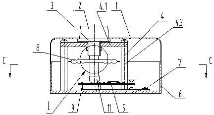
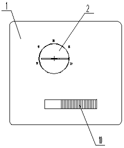
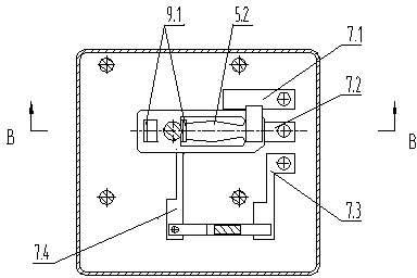
[0037] The passive adjustable temperature control switch shown in the accompanying drawings includes a box cover 1, a temperature control mechanism 3, a bracket assembly 4, a metal switch pressing piece 5, a box body 6, and a terminal 7; the box cover 1 is closed on the box body 6 The bracket assembly 4 includes a support plate 4.1 and a pillar 4.2, and the support plate 4.1 is fixedly connected in the box body 6 through the pillar 4.2; the bottom plate of the box body 6 under the temperature control mechanism 3 is fixedly connected to the support frame 9 on both sides of the vertical support plate 9.1 The metal switch pressing piece 5 is set on the supporting frame 9 supporting plate 9.1, one end of which extends out of the supporting frame 9, and the upper and lower end faces of the extending end are respectively provided with an upper...


PUM


Abstract

The invention discloses a passive adjustable temperature control switch which comprises a box cover, a temperature control mechanism, a support assembly, a metal switch pressing piece and a box body, wherein the temperature control mechanism comprises a membrane box and a vertically arranged adjusting shaft; a supporting frame is fixedly connected to the lower portion of the temperature control mechanism; the metal switch pressing piece is installed on a supporting frame supporting plate in a sleeved mode, and one end of the metal switch pressing piece stretches out of the supporting frame; a pressing piece protruding upwards and abutting against the side face of the supporting frame is arranged in the metal switch pressing piece; the membrane box is a gas expansion type temperature sensing membrane box and comprises an upper membrane, a lower membrane, an upper shaft and a lower shaft, the disc-shaped metal upper membrane is buckled with a cavity of the lower membrane oppositely, the edge of the upper membrane and the edge of the cavity of the lower membrane are sealed and connected together, and a formed sealing inner cavity is filled with gas media; the upper shaft on the top of the upper membrane is fixedly connected with the lower end of the adjusting shaft; the lower end of the lower shaft on the lower portion of the lower membrane abuts against the upper end face of the metal switch pressing piece on the supporting frame. The passive adjustable temperature control switch is not affected by network voltage large-amplitude fluctuation, small in size, low in manufacturing cost, convenient to install and capable of accurately controlling the temperature, and a power supply is not needed to be equipped in addition.

Description

technical field [0001] The invention relates to a temperature control switch, in particular to an adjustable temperature control switch. Background technique [0002] Electric heating in the modern construction industry generally uses temperature control switches to control the temperature. The temperature control switches in the prior art are divided into two categories: electronic and mechanical. Electronic temperature control switches are unstable when the power grid is lower than 170 volts. The voltage is higher than 240 volts, and the electronic components are easy to break down and cannot work normally; the mechanical temperature control switch is equipped with a bimetallic sheet, which uses the principle of thermal expansion and contraction, and the contacts directly control the power supply of the heating element. The metal sheet has a large volume and is difficult to install, resulting in a large volume of the entire temperature control switch and high manufacturing...

Claims


Application Information

Patent Timeline
IPC IPC(8): H01H37/46
Inventor 何兆来
Owner XINGHUA GALAXY INSTR
Why Eureka
Try Eureka