Eureka AIR delivers breakthrough ideas for toughest innovation challenges, trusted by R&D personnel around the world.

Novel magnetic flux adjustable permanent magnet synchronous motor

A permanent magnet synchronous motor and magnetic flux technology, applied in the direction of magnetic circuit characterized by magnetic materials, magnetic circuit rotating parts, magnetic circuit shape/style/structure, etc., can solve the problem of limited magnetic field weakening ability, permanent magnet synchronous electrical Gap flux can not be adjusted to achieve the effect of increasing the speed range and weakening the mutual influence

Inactive Publication Date: 2013-12-11
ZHEJIANG UNIV
View PDF3 Cites 30 Cited by
  • Summary
  • Abstract
  • Description
  • Claims
  • Application Information

AI Technical Summary

Problems solved by technology

[0004] The purpose of the present invention is to solve the problem that the existing permanent magnet synchronous electric gap magnetic flux cannot be adjusted, so as to reduce the problems such as the decrease of motor efficiency caused by field weakening speed regulation, the risk of field weakening out of control, and the limited field weakening capability. A Novel Flux Adjustable Permanent Magnet Synchronous Motor Structure

Method used


Image

  • Novel magnetic flux adjustable permanent magnet synchronous motor
  • Novel magnetic flux adjustable permanent magnet synchronous motor
  • Novel magnetic flux adjustable permanent magnet synchronous motor

Examples


Embodiment Construction

[0021] The present invention will be further described below in conjunction with the accompanying drawings.

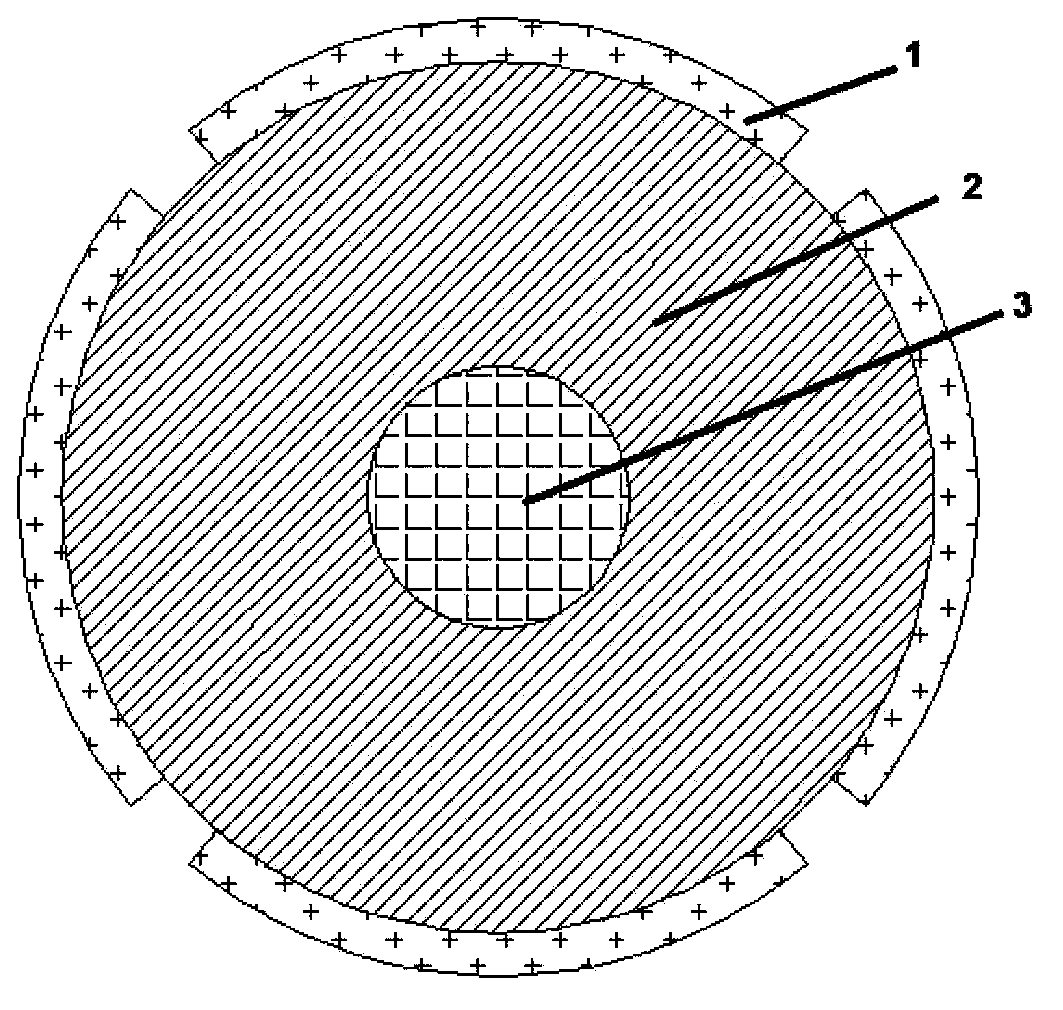
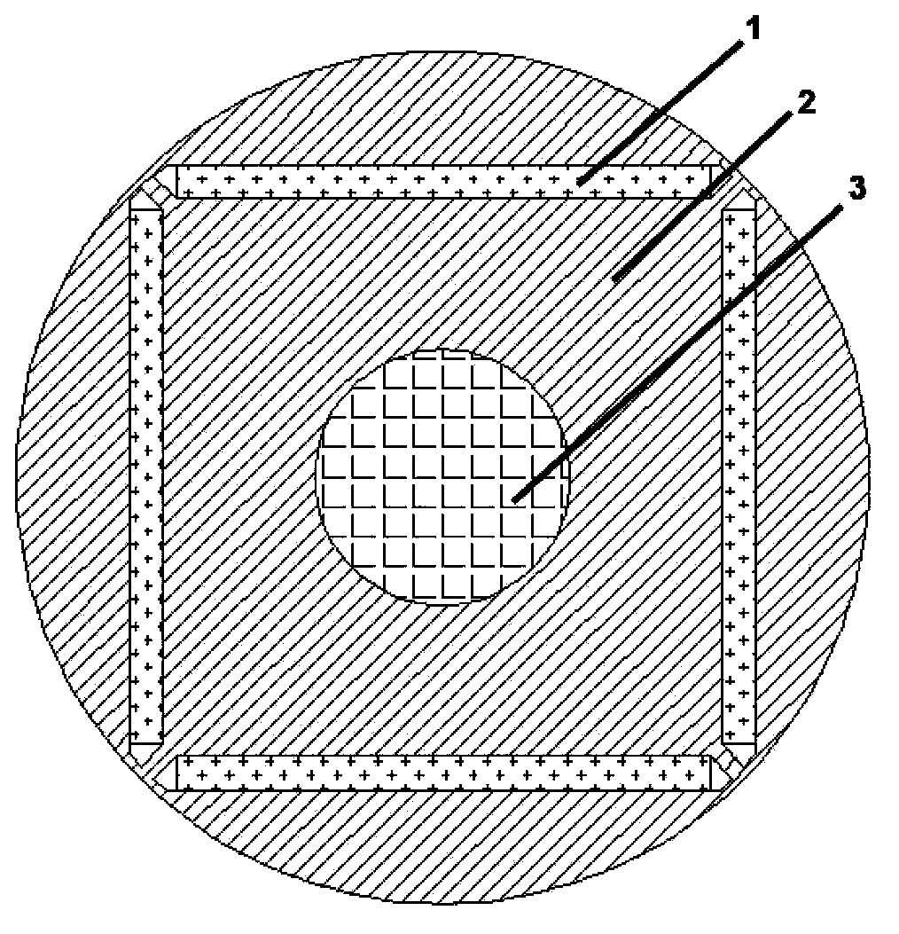
[0022] Such as figure 1 and figure 2 As shown, only high coercivity permanent magnets (such as NdFeB) are used in permanent magnet synchronous motors at present, so its air gap flux is difficult to change.

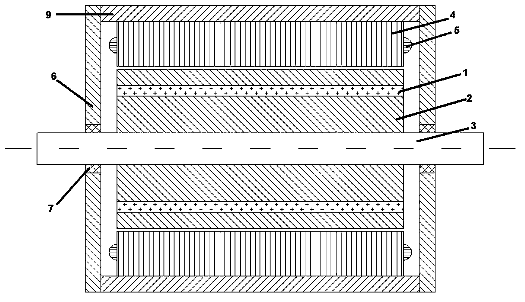
[0023] Such as image 3 and Figure 4 As shown, the present invention includes a stator core 4, a stator winding 5, a rotor core 2, a high-coercivity permanent magnet 1, a low-coercivity permanent magnet 8, a rotating shaft 3, a bearing 7, a casing 6, and an end cover 9. Since the magnetization state of low-coercivity permanent magnets (such as Alnico, ferrite) is easier to change, the combination of high-coercivity and low-coercivity permanent magnets is used to adjust the magnetization of low-coercivity permanent magnets. State, change the magnetic circuit, thereby changing the air gap flux, to achieve the purpose of adjustable flux.

[0024] 1) When the lo...


PUM


Abstract

The invention discloses a novel magnetic flux adjustable permanent magnet synchronous motor. Traditional magnetic flux weakening speed regulation has a lot of defects such as reduction of motor efficiency, risks of out of control of magnetic flux weakening and limited magnetic weakening capability. According to the novel magnetic flux adjustable permanent magnet synchronous motor, a permanent magnet is arranged under each pole of a rotor iron core, the permanent magnets are distributed in a U shape, wherein the permanent magnets with high coercivity are distributed at the bottom end of the U shape, the permanent magnets with low coercivity are distributed on the two sides of the U shape, a trapezoidal opening groove is formed above the permanent magnets with the high coercivity, and arc-shaped opening grooves are formed in the two sides of the trapezoidal opening groove. According to the novel magnetic flux controllable permanent magnet synchronous motor, due to the fact that a direct-axis current is applied to a stator winding, the magnetized state of the permanent magnets with the low coercivity can be changed, while the magnetized state of the permanent magnets with the high coercivity is not affected, thereof, the magnetic path inside the rotor is changed, the purpose of adjusting air gap magnetic flux is achieved, and the speed regulation range of the motor can be improved greatly.

Description

technical field [0001] The invention belongs to the field of motor design and relates to a novel magnetic flux adjustable permanent magnet synchronous motor. Background technique [0002] Permanent Magnet Synchronous Motor (PMSM) has significant advantages such as high efficiency and high power density. In recent years, with the continuous improvement of the performance of permanent magnet materials and the cost performance of power electronic devices, permanent magnet synchronous motors have been more and more widely used in industry, agriculture, national defense and daily life. The stator structure of the permanent magnet synchronous motor is the same as that of the DC motor and the asynchronous motor, but the rotor structure is quite different. According to the difference in the position of the permanent magnet on the rotor, the rotor magnetic circuit structure can generally be divided into three types: surface type, built-in type and claw pole type. Currently more com...

Claims


Application Information

Patent Timeline
Patent Type & Authority Applications(China)
IPC IPC(8): H02K1/27H02K1/02
Inventor 陈阳生周裕斌
Owner ZHEJIANG UNIV
Why Eureka
Eureka Blog
Learn More