Rolling tool

A rolling and tooling technology, which is applied in the direction of manufacturing tools, metal processing equipment, polishing machine tools, etc., can solve the problems of leaking fluid or emulsion, large rolling tools, loss, etc.

Inactive Publication Date: 2013-12-11
MAUSER WERKE OBERNDORF MASCHENBAU
View PDF11 Cites 7 Cited by
  • Summary
  • Abstract
  • Description
  • Claims
  • Application Information

AI Technical Summary

Problems solved by technology

[0004] The disadvantage of this type of rolling tool is considerable leakage and the corresponding loss of fluid or emulsion

Method used


Image

  • Rolling tool
  • Rolling tool
  • Rolling tool

Examples


Embodiment Construction

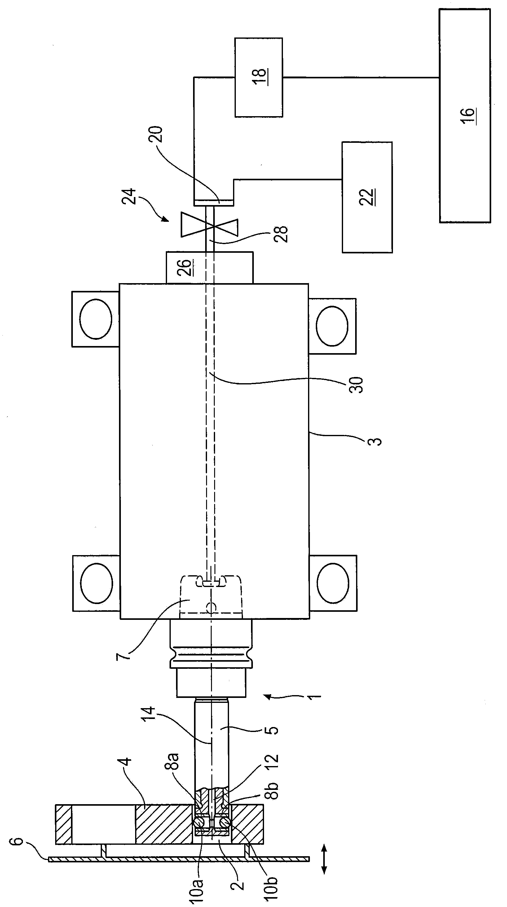
[0039] figure 1 A partial cross-sectional view and a partial schematic view of the rolling machine are shown. The rolling machine comprises a rolling tool 1 adapted to be driven in rotation relative to a stationary housing 3 .

[0040] A part 5 of the tool 1 is partially introduced into the connecting rod bore 2 of the connecting rod 4 . The connecting rod 4 is fixed to the receptacle 6 and is thus able to be displaced in translation relative to the tool 1 (according to the double arrow).

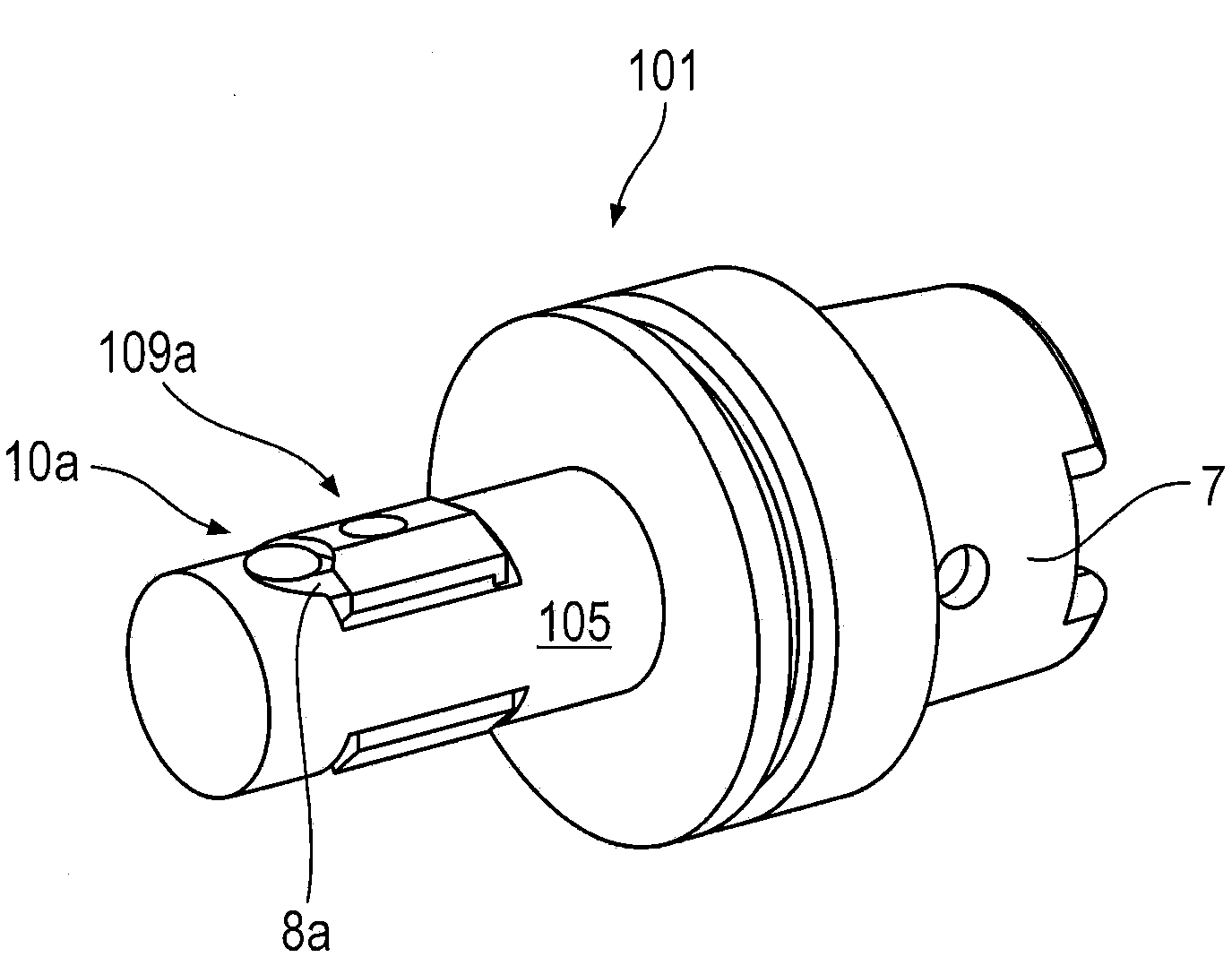
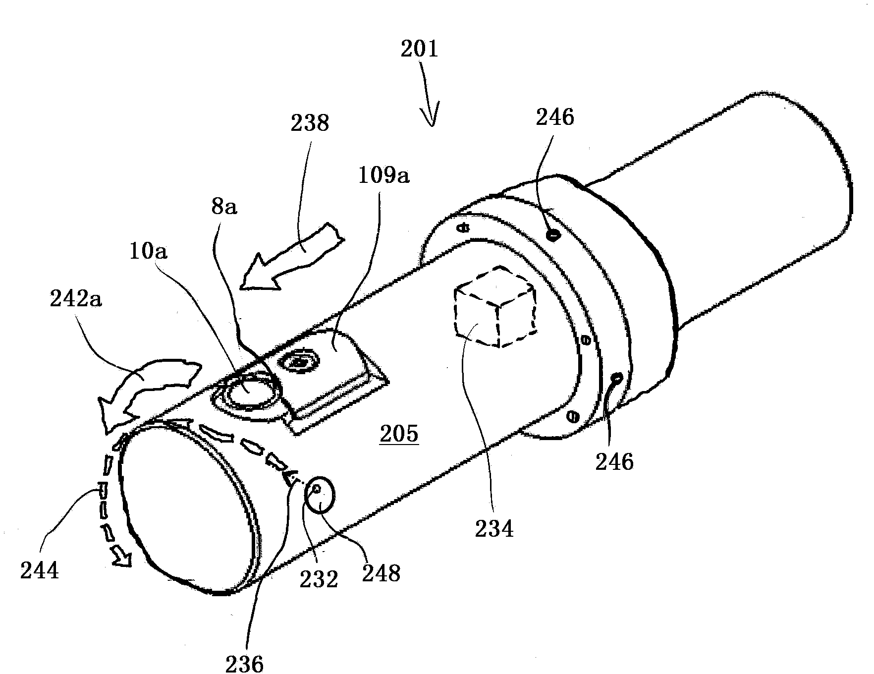
[0041] The part 5 of the tool 1 which is introduced into the connecting rod bore 2 is approximately cylindrical. Two radially extending opposite bushings 8 a , 8 b are inserted into the part 5 . At the radially outer end of part 5, a race is formed by a corresponding constraint (not in figure 1 shown in detail). The balls 10a, 10b are mainly housed in the bushings 8a, 8b, wherein the balls 10a, 10b basically have two different positions: In the unloaded position (not shown), the balls ...


PUM


Abstract

Disclosed is a rolling tool which serves for working - in particular rolling smooth - an inner lateral surface of a cylindrical clearance. For this purpose, the rolling tool has at least one rolling body, which is held in the rotatably drivable rolling tool, and can be taken along by said tool on a peripheral path along the inner lateral surface. In this case, the at least one rolling body is inserted into a radial clearance in the rolling tool and can be subjected to a pressurized fluid from the inside to the outside along the radial clearance. According to the invention, the fluid is an aerosol. The aerosol is a fluid mixed with gas and serves for hydrostatic bearing and lubrication. In this case, the amount of fluid required is reduced in comparison with the prior art - on the basis of minimal quantity lubrication (MQL).

Description

technical field [0001] The invention relates to a rolling tool according to the preamble of claim 1 and to a rolling method. Background technique [0002] Rolling tools are known for cylindrical clearances, such as connecting rod bores, in which rolling bodies roll on the inner lateral surface of the clearance with an outwardly directed pressing force. [0003] In patent specification EP1 275 472 B1 a rolling tool of this type is disclosed, in which a ball is pressed by a fluid onto the surface to be rolled. For each sphere there is provided a hydrostatic bearing to which fluid is supplied. [0004] A disadvantage of this type of rolling tool is considerable leakage and the corresponding loss of fluid or emulsion. Contents of the invention [0005] In contrast, the object of the present invention is to provide a rolling tool in which fluid or emulsion losses are reduced. [0006] This object is achieved by a rolling tool comprising the features of claim 1 and a rolling ...

Claims


Application Information

Patent Timeline
Patent Type & Authority Applications(China)
IPC IPC(8): B24B39/02
CPCB24B39/023B24B55/02Y10T29/47B24B39/003B24B39/02
Inventor 沃尔夫冈·伦普西格弗里德·格鲁勒阿尔弗雷德·奥斯特塔格
Owner MAUSER WERKE OBERNDORF MASCHENBAU
Why Eureka
Try Eureka