Shaft member for wheel rolling bearing device

A technology for supporting devices and shaft components, which is applied in the direction of wheel bearings, rolling contact bearings, and rotating bearings. It can solve the problems of decarburization, oxidation, and low dimensional accuracy, and achieve the effect of stress concentration suppression

Inactive Publication Date: 2013-12-11
JTEKT CORP
View PDF10 Cites 0 Cited by
  • Summary
  • Abstract
  • Description
  • Claims
  • Application Information

AI Technical Summary

Problems solved by technology

In the surface molded by hot forging, the dimensional accuracy is low, and oxidation and decarburization occur in the surface

Method used


Image

  • Shaft member for wheel rolling bearing device
  • Shaft member for wheel rolling bearing device
  • Shaft member for wheel rolling bearing device

Examples


Embodiment approach 1

[0031] Embodiment 1 of the present invention will refer to Figure 1 to Figure 11 to describe.

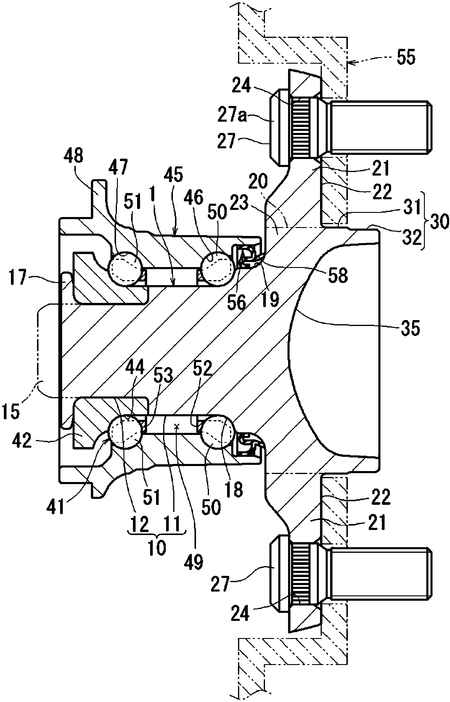
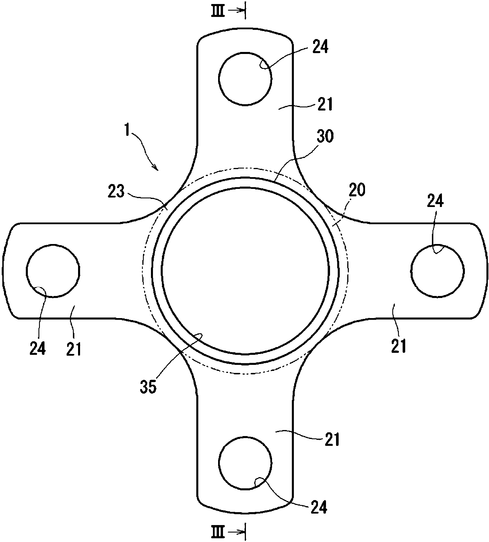
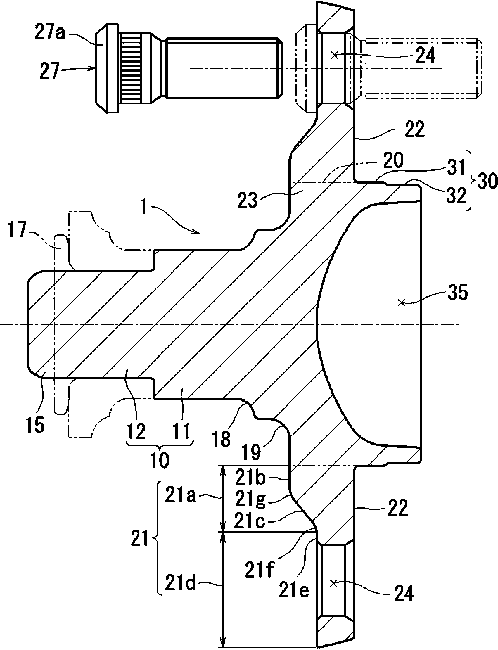
[0032] Such as figure 1 As shown, the shaft member 1 of the wheel rolling bearing device (wheel hub nut) to be used in the wheel rolling bearing device integrally includes: a shaft portion 10; a fitting shaft portion 30 formed on the shaft portion 10 On one end side, the diameter of the fitting shaft portion 30 is larger than the diameter of the shaft portion 10, and the central hole of the wheel (not shown) is to be fitted on the fitting shaft portion 30; the flange base portion 23, the the flange base 23 is located between the shaft portion 10 and the fitting shaft portion 30; radial extension.

[0033] Then, a bolt hole 24 penetrates through each of the plurality of flange portions 21 , and hub bolts 27 for fastening the wheel are to be placed in the bolt hole 24 by press insertion.

[0034] In the fitting shaft portion 30, the brake rotor fitting portion 31 corresponding to...


PUM


Abstract

[Problem] To suppress localized concentration of stress (stress concentration) generated in a flange section, formed by cold forging, by the input of a load into the flange section, in a shaft member for a wheel rolling bearing device. [Solution] A flange section formed by cold forging comprises an outward flange section and an inward flange section. The inward flange section viewed in a shaft line direction cross-section is formed thicker than the outward flange section and the flange surface shape on the side where a bolt seat surface section (27a) is arranged comprises, at a radial direction base section position, a convex curve shape connected to the outward flange section, as the flange surface shape from the base section position of the vertical surface shape of a constant length in the radial direction to the outward flange section, and a convex curved section (21i) that is joined contiguously to the concave curved section (21h), on the radially inward side relative to the concave curved section (21h). The radius of curvature (R3) for the convex curved section (21i) is smaller than the radius of curvature (R2) for the concave curved section (21h).

Description

technical field [0001] The invention relates to a shaft member of a wheel rolling bearing. Background technique [0002] Generally, for example, disclosed and known in Patent Document 1 and Patent Document 2 is a shaft member of a wheel rolling bearing device, which includes: a shaft portion in which an inner ring raceway surface is formed on an outer peripheral surface; a fitting shaft portion formed on one end side of the shaft portion; and a plurality of flange portions located between the shaft portion and the fitting shaft portion and extending in the radial direction The outer direction extends radially, and a bolt hole in which a hub bolt is placed is formed through each of the plurality of flange portions. The shaft members of the wheel rolling bearing devices disclosed in Patent Document 1 and Patent Document 2 are each molded by a lateral extrusion process in cold forging. Therefore, weight can be reduced compared with a conventional flange portion formed in a di...

Claims


Application Information

Patent Timeline
Patent Type & Authority Applications(China)
IPC IPC(8): B60B27/00B21K1/05B60B35/02F16C33/58
CPCB21K1/05B21K1/40B60B27/00B60B35/025B60B2380/75B60B2380/82F16C19/186F16C33/581F16C2240/60F16C2326/02
Inventor 增田善纪奥村刚史
Owner JTEKT CORP
Why Eureka
Try Eureka