Combustion burner, solid-fuel-combustion burner, solid-fuel-combustion boiler, boiler, and method for operating the boiler
A solid fuel and burner technology, which is applied in the combustion method, non-flammable liquid/gas transportation, burner, etc., can solve the problems of difficulty in fully exerting the flame stabilization capability of the front end of the flame stabilizer, and difficulty in setting operating parameters.
- Summary
- Abstract
- Description
- Claims
- Application Information
AI Technical Summary
Problems solved by technology
Method used
Image
Examples
Embodiment 1
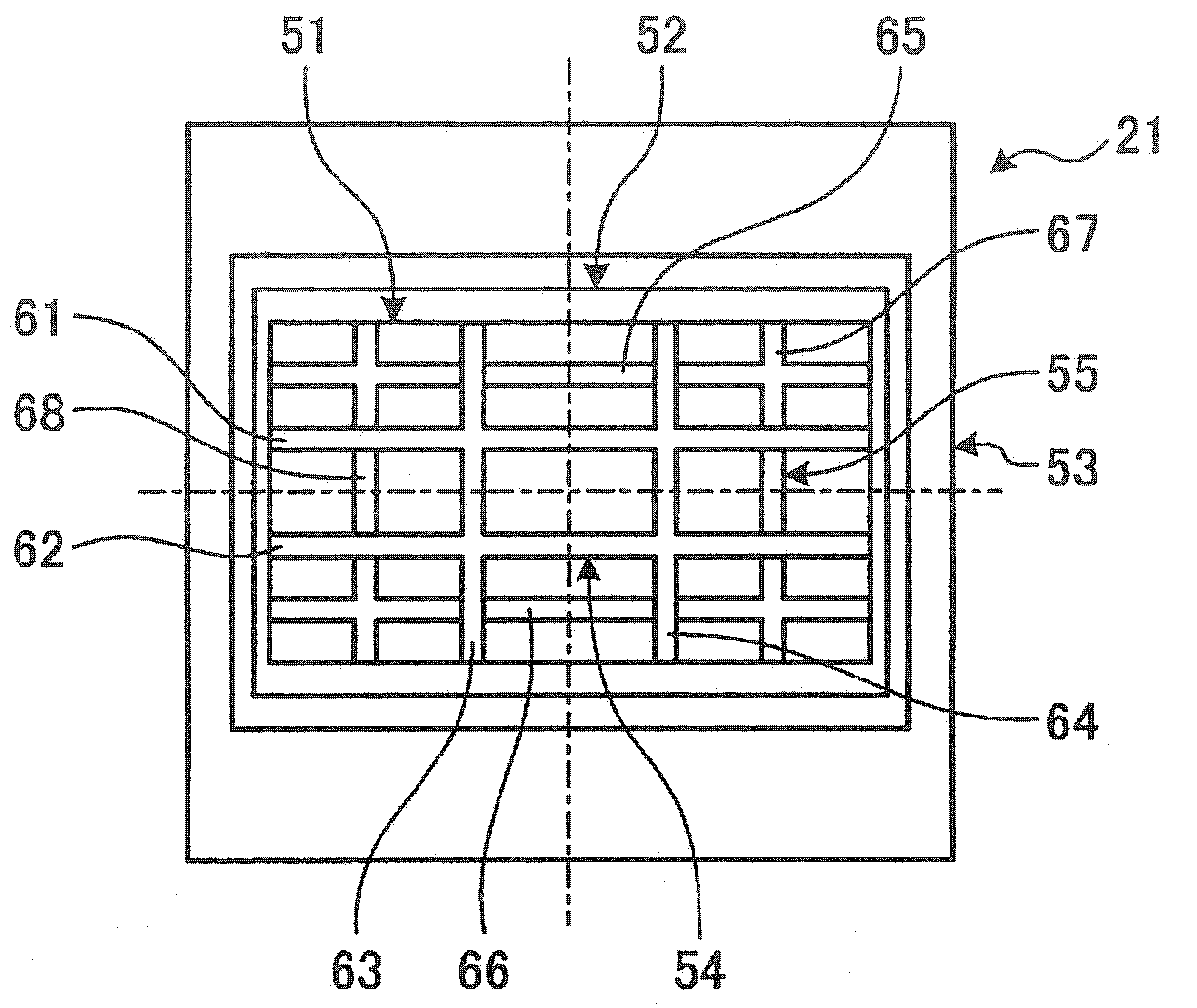
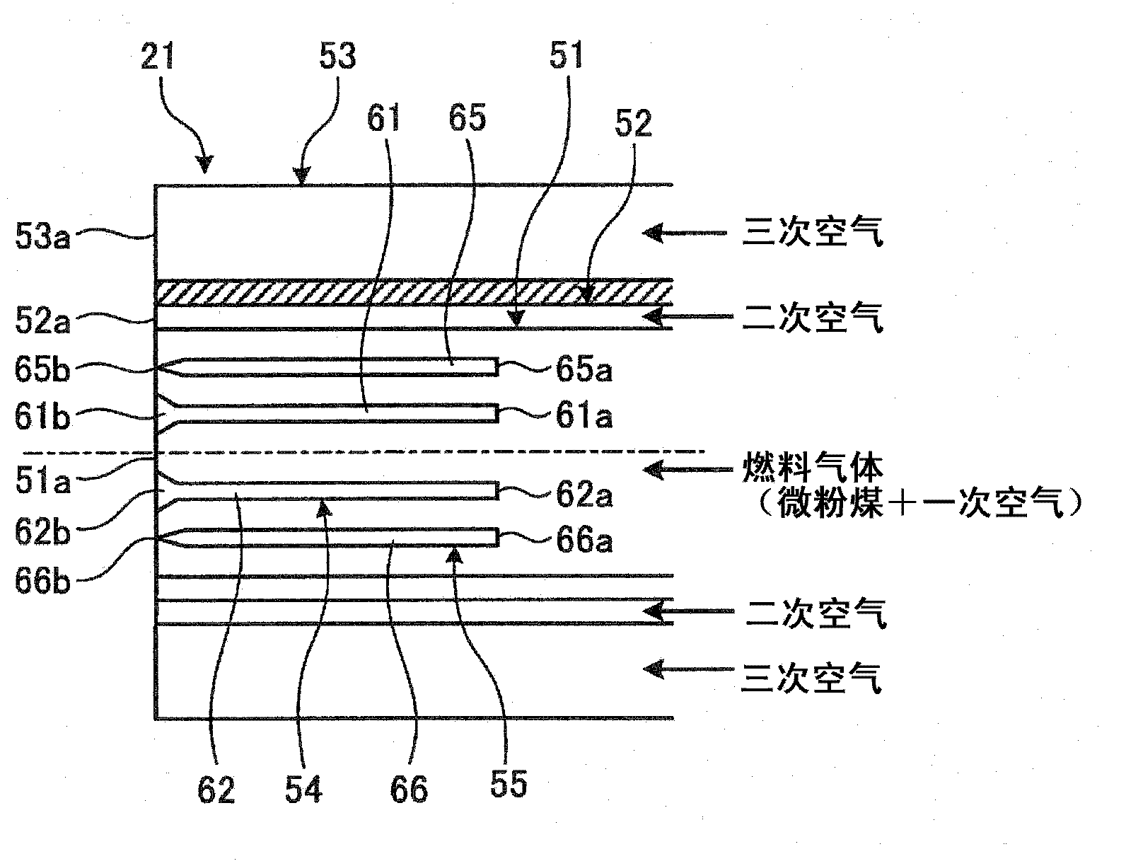
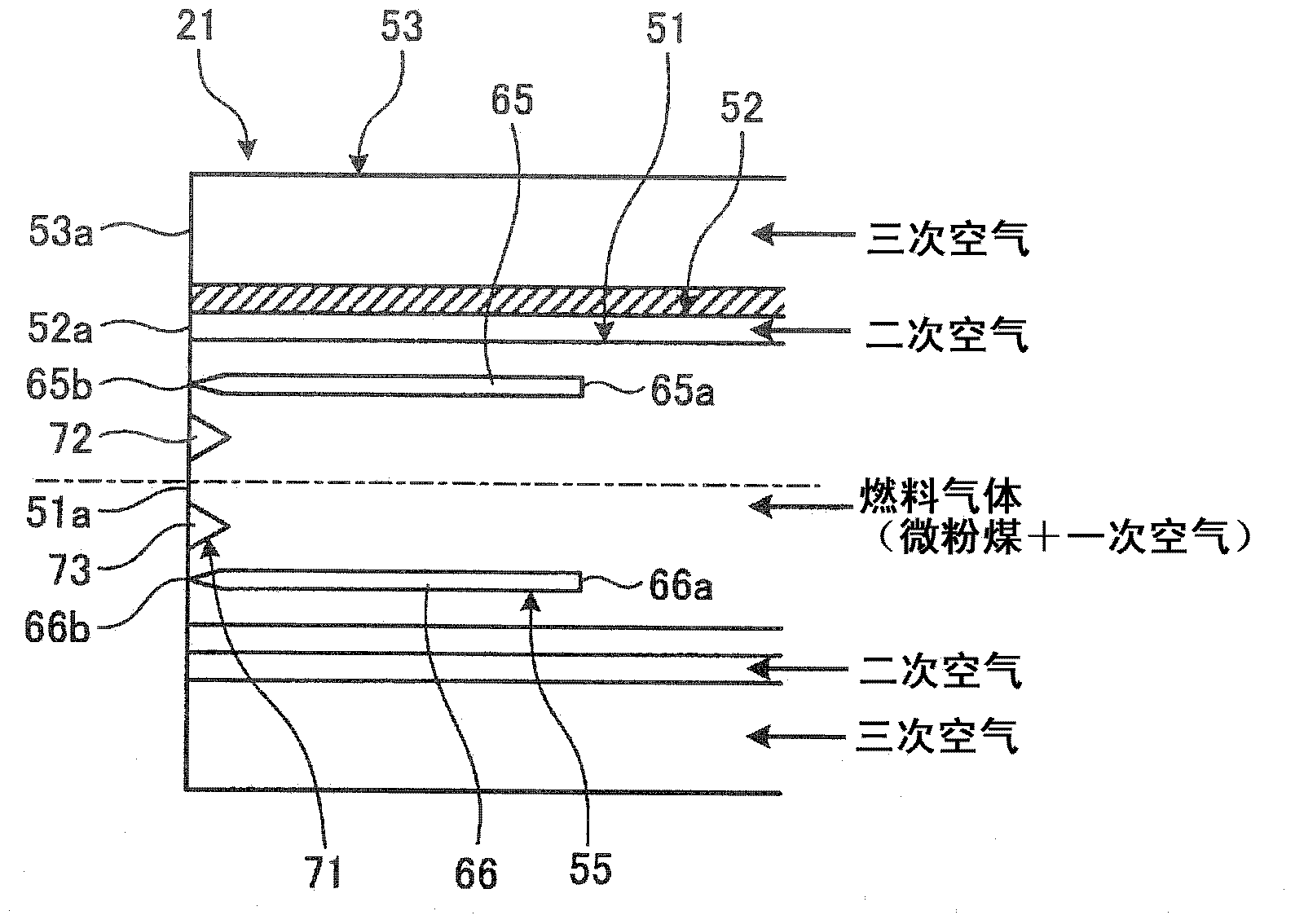
[0168] As a burner of a conventional pulverized coal-fired boiler, there is a technique described in Patent Document 1 mentioned above. In the combustion device described in Patent Document 1, by providing a flame stabilizer between the center and the outer periphery of the pulverized coal injection hole (primary flow path), the concentrated flow of pulverized coal can collide with the flame stabilizer. Stable low NOx combustion can be performed in a large load range.
[0169] However, in this conventional combustion device, when the fuel gas of pulverized coal and air collides with the flame stabilizer, the airflow peels off at the rear end of the flame stabilizer, and it is difficult to fully exert the flame stabilization at the front end of the flame stabilizer. ability. In addition, in the flow path where the fuel gas of pulverized coal and air circulates, in the vicinity of the flame stabilizer, the cross-sectional area of the flow path is reduced due to the flame stabili...
Embodiment 2
[0231] Picture 11 It is a cross-sectional view showing a burner of Example 2 of the present invention. It should be noted that components having the same functions as those in the above-mentioned embodiments are denoted by the same symbols and detailed descriptions are omitted.
[0232] In the burner of Example 2, such as Picture 11 As shown, in the combustor 21, a fuel nozzle 51, a secondary air nozzle 52, and a tertiary air nozzle 53 are provided from the center side, and a flame stabilizer 121 is provided. Furthermore, a rectifying member 122 is provided between the inner wall surface of the fuel nozzle 51 and the flame stabilizer 121.
[0233] The flame stabilizer 121 is arranged at the axial center of the fuel nozzle 51 in a horizontal direction, and its structure is substantially the same as the first flame stabilizer members 61 and 62 described in the first embodiment. That is, the flame stabilizer 121 has a widened portion whose width is widened toward the downstream sid...
Embodiment 3
[0239] Picture 12 It is a cross-sectional view showing a burner of Example 3 of the present invention. It should be noted that components having the same functions as those in the above-mentioned embodiments are denoted by the same symbols and detailed descriptions are omitted.
[0240] In the burner of Example 3, such as Picture 12 As shown, in the combustor 21, a fuel nozzle 51, a secondary air nozzle 52, and a tertiary air nozzle 53 are provided from the center side, and a flame stabilizer 131 is provided. In addition, a rectifying member 135 is provided inside the flame stabilizer 131.
[0241] The flame stabilizer 131 is arranged in the axial center portion of the fuel nozzle 51 in a horizontal direction, and two flame stabilizers in the horizontal direction and two flame stabilizers in the vertical direction are arranged in a crossing manner. In addition, the rectification member 135 has: a first rectification member 136 that is located between the flame stabilizers in the...
PUM
 Abstract
Description
Claims
Application Information
 - R&D
- Intellectual Property
- Life Sciences
- Materials
- Tech Scout
- Unparalleled Data Quality
- Higher Quality Content
- 60% Fewer Hallucinations
Browse by: Latest US Patents, China's latest patents, Technical Efficacy Thesaurus, Application Domain, Technology Topic, Popular Technical Reports.
© 2025 PatSnap. All rights reserved.Legal|Privacy policy|Modern Slavery Act Transparency Statement|Sitemap|About US| Contact US: help@patsnap.com


