
Prestressed Loading Device of Internal Support System of Foundation Pit Support

A support system and foundation pit support technology, which is applied in basic structure engineering, excavation, construction, etc., can solve the problems of non-reusable, low support stiffness, and difficult to control deformation, so as to save construction costs, large construction space, The effect of convenient construction

Active Publication Date: 2016-05-11
杭州爱默乐实验设备有限公司
View PDF10 Cites 0 Cited by
  • Summary
  • Abstract
  • Description
  • Claims
  • Application Information

AI Technical Summary

Problems solved by technology

Since the steel support structure currently used mainly uses a single section steel or steel pipe as a support beam, there is no effective connection between each section steel or steel pipe, and it cannot work as a composite structure, so their support stiffness is relatively low. The force it can withstand is relatively limited. For foundation pits with large spans, it is difficult to control their deformation with the current steel support support
Because many of these supports are made according to the requirements of on-site construction, there is no standardized connection size, and the purpose of interchangeability and universal use between various parts cannot be achieved. After the foundation pit construction is completed, most of the support parts have become disposable consumables. , cannot be reused
[0003] At present, after the foundation pit support is completed, there is no prestress application process, or adding supports, which cannot further improve the overall stiffness of the support system after the support system is assembled.

Method used


Image

  • Prestressed Loading Device of Internal Support System of Foundation Pit Support
  • Prestressed Loading Device of Internal Support System of Foundation Pit Support

Examples


Embodiment 1

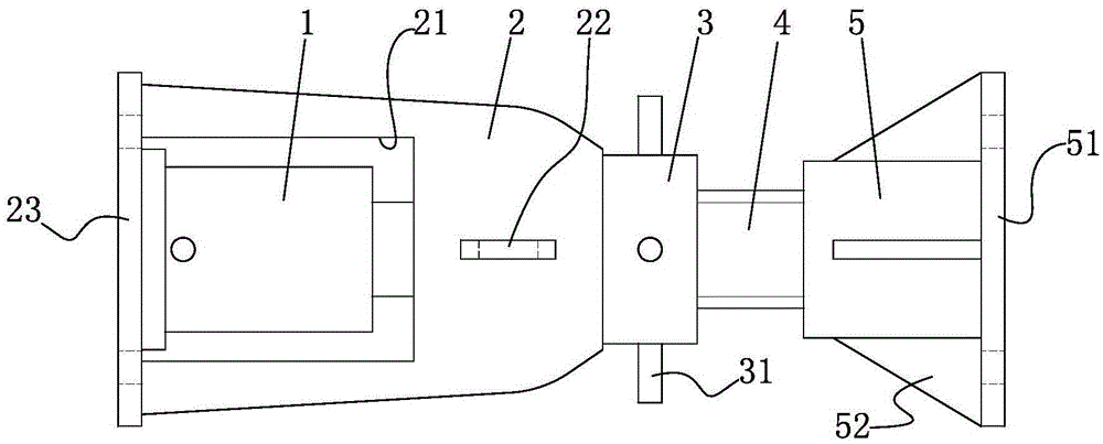
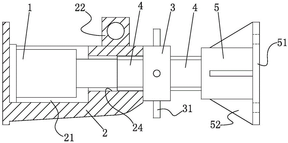
[0017] like figure 1 , figure 2 The prestressed loading device of the inner support system of the foundation pit support includes a jack 1 and a connecting part, and the connecting part includes a loading seat 2, a nut 3, a screw 4 and a screw base 5, and the loading seat 2 is provided for placing The groove 21 of the jack 1, one side of the groove 21 is a screw socket 24, the screw 4 is inserted in the screw socket 24, and the loading seat 2 is provided with a connecting flange A23 on the opposite side of the screw socket 24, and the groove 21 The jack 1 is placed inside, the top strut of the jack 1 is inserted into the screw socket 24 and is offset against one end of the screw 4, and the other end of the screw 4 is fixedly connected with the screw base 5, and the screw base 5 is provided with a connection on the opposite side of the connecting screw 4. The flange B51 and the nut 3 capable of abutting against the loading seat 2 are threadedly connected to the part of the sc...


PUM


Abstract

The invention discloses a prestress loading device of an internal support system for foundation pit supporting. The prestress loading device comprises a jack and a connecting component, wherein the connecting component comprises a loading seat, a screw nut, a screw rod and a screw rod base, a groove for placing the jack is formed in the loading seat, a screw rod insertion hole is formed in one side of the groove, the screw rod is inserted in the screw rod insertion hole, a connecting flange A is arranged at the side, opposite to the screw rod insertion hole, of the loading seat, the jack is placed in the groove, a jacking rod of the jack is inserted in the screw rod insertion hole and is abutted against one end of the screw rod, the other end of the screw rod is fixedly connected with the screw rod base, and a connecting flange B is arranged at the side, opposite to the connected screw rod, of the screw rod base and can be in threaded connection with the screw nut, abutted against the loading seat, at a portion outside the screw rod insertion hole of the screw rod. According to the prestress loading device of the internal support system for the foundation pit supporting, prestress is applied to an entire supporting structure, so that the overall strength of the support system is improved; the disassembly is convenient, and the prestress loading device can be repeatedly used, so that the aims of reducing the construction cost and facilitating the construction are reached.

Description

technical field [0001] The invention relates to the technical field of civil engineering, in particular to a prestress loading device for an inner support system of foundation pit support. Background technique [0002] In soft soil deep foundation pit engineering, reinforced concrete or steel pipe supports the support structure. In order to reduce the deformation of the foundation pit and increase the stability, the commonly used methods are: increase the size of the reinforced concrete purlin street surface, increase the number of steel pipe supports, Reduce spacing etc. But this will greatly increase the consumption of building materials and also reduce the effective construction space in the foundation pit. Since the steel support structure currently used mainly uses a single section steel or steel pipe as a support beam, there is no effective connection between each section steel or steel pipe, and it cannot work as a composite structure, so their support stiffness is r...

Claims


Application Information

Patent Timeline
Patent Type & Authority Patents(China)
IPC IPC(8): E02D17/04
Inventor 高尔荣
Owner 杭州爱默乐实验设备有限公司
Learn More