
A disc-cooled high-power magneto-rheological clutch

A high-power, magneto-rheological technology, applied in the direction of fluid clutches, clutches, mechanical equipment, etc., can solve problems such as difficult high-power transmission, increase in magnetic circuit reluctance, and magneto-rheological clutches do not consider heat dissipation, and achieve heat dissipation effects Good, to avoid bad heat dissipation, to achieve the effect of high power transmission

Inactive Publication Date: 2017-01-04
CHINA UNIV OF MINING & TECH
View PDF6 Cites 0 Cited by
  • Summary
  • Abstract
  • Description
  • Claims
  • Application Information

AI Technical Summary

Problems solved by technology

The working temperature of the magneto-rheological fluid is certain. If it does not dissipate heat, it will exceed its working temperature, causing the magneto-rheological clutch to fail, and at the same time limiting the transmission power of the clutch.
[0004] At present, there are many patents related to magneto-rheological soft starters, such as: the Chinese patent "radial self-pressurized magnetorheological fluid clutch" published on January 16, 2002 (application number: 00104451.6, publication number: 1331389), The magneto-rheological clutch does not consider the problem of heat dissipation and cannot realize high-power transmission; the Chinese patent "a water-cooled magneto-rheological soft starter" published on February 22, 2012 (application number: CN201110334597.X, publication number: 102359513A ), which uses the internal cooling method of the transmission ring to dissipate heat, but because the inside of the transmission ring is hollow, it will increase the reluctance of the magnetic circuit, and it is difficult to achieve high-power transmission

Method used


Image

  • A disc-cooled high-power magneto-rheological clutch
  • A disc-cooled high-power magneto-rheological clutch

Examples


Embodiment Construction

[0020] The present invention will be further described below in conjunction with accompanying drawing.

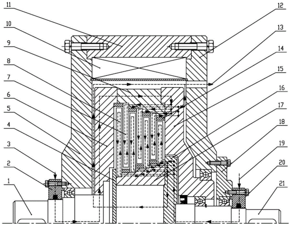
[0021] Such as figure 1 As shown, the disc-cooled high-power magneto-rheological clutch includes a main transmission shaft 1, a slave transmission shaft 21, a left fixed magnetic conduction shell 5, a middle fixed magnetic conduction shell 11, a right fixed magnetic conduction shell 12, a left rotation guide Magnetic side plate 6, main rotating magnetic isolation shell 9, right rotating magnetic side plate 15, excitation coil 10, main friction disc group 7, slave friction disc group 8, left driven baffle plate 4, right driven connecting plate 16 , From the rotating magnetic isolation shell 17, the magnetic isolation ring group 14 and the fixed bearing seat 18;

[0022] The left-rotation magnetic conduction side plate 6 and the right-rotation magnetic conduction side plate 15 are connected with the main transmission shaft 1, and the outsides of the left-rotation magnetic co...


PUM


Abstract

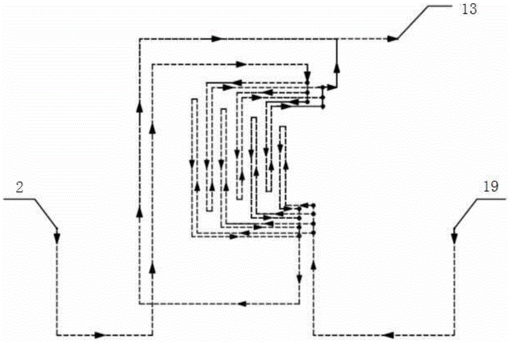
The invention discloses a cooling type large-power magnetorheological clutch in a disc. The cooling type large-power magnetorheological clutch comprises a master transmission shaft (1), a slave transmission shaft (21), a fixed magnetic-permeable shell, a left rotating magnetic-permeable side plate (6), a master rotating magnetic-isolating shell (9), a right rotating magnetic-permeable side plate (15), an exciting coil (10), a master friction disc group (7), a slave friction disc group (8), a left driven baffle (4), a right driven connecting plate (16), a slave rotating magnetic-isolating shell (17), a magnetic-isolating ring group (14) and a fixed bearing seat (18). The clutch is provided with water inlets and a water outlet; all the friction discs are internally provided with water inlet channels and water outlet channels; cooling water channels penetrating through the water inlet channels and the water outlet channels are arranged between the water inlets and the water outlet. The cooling type large-power magnetorheological clutch disclosed by the invention has the advantages that the mode of introducing water in the disc is adopted for cooling, all the friction discs and the parts by which cooling water channels pass can be radiated, the radiating effect is good, the condition of failure of the magnetorheological clutch can be avoided and further the large-power transmission can be realized.

Description

technical field [0001] The invention relates to a magneto-rheological clutch, in particular to a disc-cooled high-power magneto-rheological clutch. Background technique [0002] Magnetorheological fluid is a typical smart material, which is mainly composed of soft magnetic particles, base carrier fluid and surface additives. The fiber-like chains hinder the free flow of the base carrier fluid, making the magnetorheological fluid change from a Newtonian fluid to a viscoplastic fluid with a certain shear force, and a strong "curing" phenomenon occurs; when the external magnetic field disappears, The magnetorheological fluid returns to a free-flowing state (liquid state). Because of this characteristic, magnetorheological fluid has been widely used in products such as clutches, brakes, dampers, shock absorbers, polishing devices and composite components. [0003] Among them, the magnetorheological clutch is a new type of power transmission technology developed with magnetorhe...

Claims


Application Information

Patent Timeline
Patent Type & Authority Patents(China)
IPC IPC(8): F16D37/02
Inventor 田祖织吴向凡陈飞
Owner CHINA UNIV OF MINING & TECH
Learn More