
Compression Container Unit

A compression device and container technology, applied in the pipeline system, mechanical equipment, gas/liquid distribution and storage, etc., can solve the problems of wasting time, high production cost, inconvenient disassembly and relocation, etc., and achieve convenient use, reasonable structure, The effect of saving production operation time

Active Publication Date: 2015-09-02
CNPC XIBU DRILLING ENG
View PDF3 Cites 0 Cited by
  • Summary
  • Abstract
  • Description
  • Claims
  • Application Information

AI Technical Summary

Problems solved by technology

[0003] The present invention provides a compression container device, which overcomes the above-mentioned deficiencies in the prior art, and can effectively solve the problem of installation, disassembly and relocation of the existing natural gas transportation and purification device Problems of inconvenience, waste of time, and high production costs

Method used


Image

  • Compression Container Unit

Examples


Embodiment Construction

[0010] The present invention is not limited by the following examples, and specific implementation methods can be determined according to the technical solutions of the present invention and actual conditions.

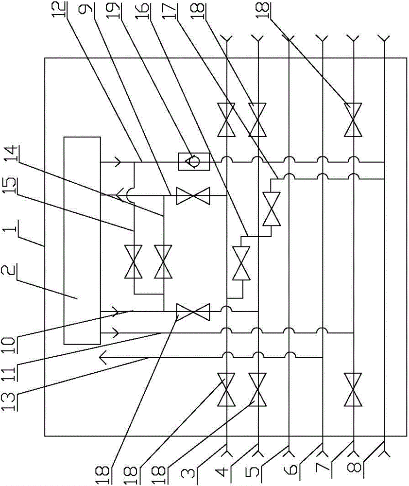
[0011] In the present invention, for the convenience of description, the description of the relative positional relationship of each component is based on the description attached to the description. figure 1 For example, the positional relationship of top, bottom, left, right, etc. is determined according to the layout direction of the drawings in the specification.

[0012] Below in conjunction with embodiment and accompanying drawing, the present invention will be further described:

[0013] as attached figure 1 As shown, the compression container device includes a compression container 1, a compressor 2, a compressor feed gas inlet pipeline 3, a compressed natural gas discharge pipeline 4, a fuel natural gas delivery pipeline 5, a compressed air delivery...


PUM


Abstract

The invention relates to the technical field of container devices, which is a compressed container device, which includes a compressed container, a compressor, a feed gas inlet pipeline for the compressor, a compressed natural gas discharge pipeline, a fuel natural gas delivery pipe, a compressed air delivery pipeline, and a compression device sewage discharge pipeline and compression device venting pipelines; compressors, compressor feed gas inlet pipelines, compressed natural gas discharge pipelines, fuel natural gas delivery pipes, compressed air delivery pipelines, compression unit blowdown pipelines and compression unit venting lines are fixedly installed in the compression container. The present invention has a reasonable and compact structure and is easy to use. By arranging the compressor and all its auxiliary pipelines in the container, it is convenient for relocation, and the quick connector of the pipeline and the quick socket of the cable arranged on the container are convenient for the installation and disassembly of subsequent operations. The production operation time is saved, and the device can be used repeatedly in production, which effectively reduces the production cost.

Description

technical field [0001] The invention relates to the technical field of container devices, and relates to a compressed container device. Background technique [0002] At present, in oil field production, natural gas is generally pretreated at the wellhead and then enters the primary pipeline network and is transported to the centralized processing station for purification before entering the long-distance pipeline network. At present, when transporting or purifying natural gas, all the devices used need to lay the foundation first, and then fix the device to the floor. In this way, in the production and construction process, not only waste of time, but also bring troubles to installation, disassembly and relocation Great inconvenience, at the same time, increased production costs. Contents of the invention [0003] The present invention provides a compression container device, which overcomes the shortcomings of the above-mentioned prior art, and can effectively solve the ...

Claims


Application Information

Patent Timeline
Patent Type & Authority Patents(China)
IPC IPC(8): F17D1/02
Inventor 吕新农赵永明王跃文张军米红学
Owner CNPC XIBU DRILLING ENG
Learn More