Sample containing device for cone calorimeter and method for measuring fused solid and liquid samples by using same

A technology of cone calorimeter and holding device, which is applied in measurement devices, chemical analysis by combustion, instruments, etc., can solve the problems of difficulty in guaranteeing the radiation intensity of samples, inability to guarantee test accuracy, and difficulty in guaranteeing the accuracy of results. , to achieve good thermal insulation effect, avoid errors, and promote accurate results.

Active Publication Date: 2013-12-18
NAT POLYMER MATERIALS IND INNOVATION CENT CO LTD
View PDF5 Cites 11 Cited by
  • Summary
  • Abstract
  • Description
  • Claims
  • Application Information

AI Technical Summary

Problems solved by technology

When the cone calorimeter tests a liquid sample or a sample that melts and drips when it is burned, the test will be inaccurate and the repeatability will be poor due to the failure of the device described in ISO:5660-2002 or the loss of mass during combustion
[0003] For the current testing of powder or liquid samples, patent CN102175718A discloses a method for measuring the combustion performance of powder or liquid samples with a cone calorimeter, and specifically discloses a device for this test method, a specific box Crucible, but this device has poor heat insulation and serious heat loss, which affects the accuracy of the test results; and the sq

Method used


Image

  • Sample containing device for cone calorimeter and method for measuring fused solid and liquid samples by using same
  • Sample containing device for cone calorimeter and method for measuring fused solid and liquid samples by using same
  • Sample containing device for cone calorimeter and method for measuring fused solid and liquid samples by using same

Examples


Example Embodiment

[0038] Example 1

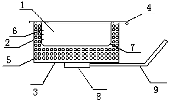
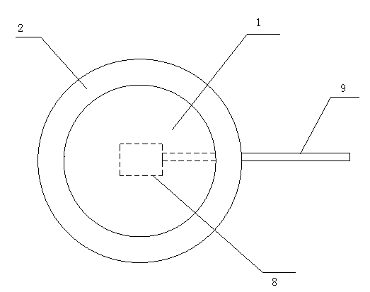
[0039] The structure of the sample holding device for the cone calorimeter in this embodiment is as follows figure 1 with figure 2 Shown. It comprises a cavity 1 and side walls 2 and a bottom wall 3 enclosing the cavity 1. The cross section of the cavity is circular; the device is also provided with a movable baffle 4 for covering the cavity. The side walls 2 and the bottom wall 3 are provided with cavities inside, and the cavities are filled with ceramic fiber cotton 5 for heat insulation. A scale 6 is provided on one side of the side wall 2 enclosing the cavity 1, the height of the cavity is 60mm, the zero point of the scale 6 is located on the bottom wall of the cavity, and the maximum scale is 40mm. A rounded corner 7 is provided at the junction of the side wall 2 and the bottom wall 3. A base 8 is provided in the center of the outer side of the bottom wall 3. The base 8 is connected to a handle 9 with a length of 100-160mm and a width of 35-55mm.

Example Embodiment

[0040] Example 2

[0041] By adopting the test method designed by the invention, the cone calorimeter test can be directly carried out on oily substances. Using the sample holding device for the cone calorimeter described in Example 1, proceed as follows:

[0042] S1. Preheat the cone calorimeter and calibrate it in accordance with the standard method ISO5660-2002;

[0043] S2. Put the sample of the workshop oil to be tested directly into the cavity until the scale shows 10mm, and cover the movable baffle;

[0044] S3. Set the required radiation intensity, perform a baseline scan, and place the sample holding device containing the sample to be tested on the weighing device of the cone calorimeter in step S2. After the reading of the weighing device is stable, turn it on The movable baffle and radiation cone are tested.

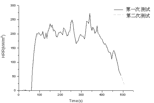
[0045] The tested HRR curve is as image 3 Shown from image 3 It can be seen that the two results of the test using the device and method of the present invention ha...

Example Embodiment

[0046] Example 3

[0047] By adopting the test method designed by the invention, the cone calorimeter test can be directly performed on the solid that will melt during combustion. Using the sample holding device for the cone calorimeter described in Example 1, proceed as follows:

[0048] S1. Preheat the cone calorimeter and calibrate it in accordance with the standard method ISO5660-2002;

[0049] S2. The solid sample to be tested is made to match the cross-sectional area of ​​the cavity, and then added to the cavity, and the movable baffle is covered;

[0050] S3. Set the required radiation intensity, perform a baseline scan, and place the sample holding device containing the sample to be tested on the weighing device of the cone calorimeter in step S2. After the reading of the weighing device is stable, turn it on The movable baffle and the radiation cone are tested.

[0051] At the same time, the measurement device described in ISO5660-2002 and the sample holding device of the pre...


PUM

PropertyMeasurementUnit
Heightaaaaaaaaaa
Lengthaaaaaaaaaa
Widthaaaaaaaaaa

Abstract

The invention discloses a sample containing device for a cone calorimeter and a method for measuring fused solid and liquid samples by using the same. The sample containing device comprises a containing cavity, side walls for enclosing the containing cavity and a bottom wall, wherein the cross section of the containing cavity is circular; the sample containing device is further provided with a movable baffle for shielding the containing cavity; the interiors of the side walls and/or the bottom wall form a cavity; the cavity is internally provided with a high-temperature-resisting heat-insulation filler layer; scales are arranged on one side of the containing cavity enclosed by the side walls. The sample containing device disclosed by the invention is especially suitable for determining powder and liquid samples by matching with the cone calorimeter; the structure guarantees that the samples can be heated uniformly in the detection process and the testing accuracy is improved; the sample containing device is easy to clean and is good in heat-insulation effect; the testing method does not need to use an aluminum foil so that the cost is saved and sample preparation is simplified; meanwhile, an error caused by combusting the aluminum foil in the testing process is reduced and the testing is accurate.

Description

technical field [0001] The invention belongs to the field of material combustion performance analysis, in particular to a sample holding device for a cone calorimeter and a method for measuring molten solid and liquid samples by using the device. Background technique [0002] With economic development and social progress, the frequency of fires and the losses they cause are also increasing. Nowadays, the loss caused by fire every year cannot be counted, so people pay more and more attention to the research of fire. The test environment of the cone calorimeter is considered to be the most representative of the combustion environment of the actual fire. Since it was launched by the National Institute of Standards and Technology NIST (formerly the National Bureau of Standards NBS) in 1982, it has been adopted by more and more laboratories around the world. Adoption, the function of the instrument is more and more perfect. The cone calorimeter can classify the combustion haza...

Claims


Application Information

Patent Timeline
IPC IPC(8): G01N31/12G01D21/02
Inventor 宋翠翠庞承焕吴博袁绍彦饶湘
Owner NAT POLYMER MATERIALS IND INNOVATION CENT CO LTD
Why Eureka
Try Eureka