Electrical circuit for operating transceiver unit, has non-linear two-terminal device, which couples pulse generation unit and resonant circuit, where resonant circuit has inductance and capacitance, which are connected in series

A technology for measuring amplifiers and energy storage, which can be used in the direction of vibrating fluids, measuring devices, and reradiation of sound waves, and can solve problems such as low ohms

Active Publication Date: 2013-12-18
ROBERT BOSCH GMBH
View PDF6 Cites 1 Cited by
  • Summary
  • Abstract
  • Description
  • Claims
  • Application Information

AI Technical Summary

Problems solved by technology

Said fluctuations are therefore particularly problematic since both oscillatory circuits are relatively low-ohmic and therefore remain in place for a long time

Method used


Image

  • Electrical circuit for operating transceiver unit, has non-linear two-terminal device, which couples pulse generation unit and resonant circuit, where resonant circuit has inductance and capacitance, which are connected in series
  • Electrical circuit for operating transceiver unit, has non-linear two-terminal device, which couples pulse generation unit and resonant circuit, where resonant circuit has inductance and capacitance, which are connected in series
  • Electrical circuit for operating transceiver unit, has non-linear two-terminal device, which couples pulse generation unit and resonant circuit, where resonant circuit has inductance and capacitance, which are connected in series

Examples


Embodiment Construction

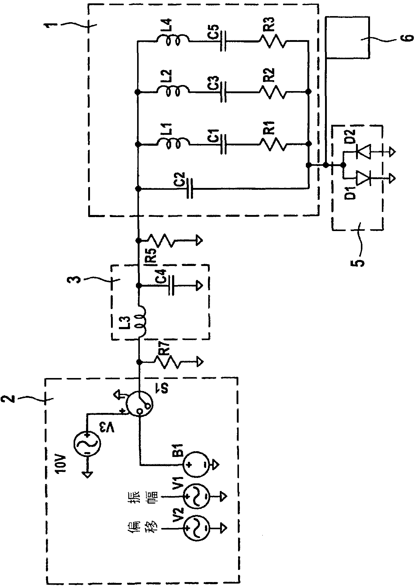
[0018] figure 1A circuit diagram of a circuit for operating the transceiver unit 1 without the measures provided according to the invention for preventing or reducing fluctuations is shown. The pulse generating unit 2 is connected to the first oscillating circuit 3 via a grounded resistor R7 , the first oscillating circuit 3 comprising an inductance L3 and a grounded capacitor C4 . The first resonant circuit 3 is connected on the output side to a second resistor R5 which is likewise connected to ground. The transceiver unit 1 is connected downstream of the second resistor R5 , which is connected to ground on the other side via a non-linear two-terminal network 5 . A measuring amplifier 6 is connected between the transceiver unit 1 and the non-linear two-terminal network 5 . The equivalent circuit diagram of the transceiver unit 1 is represented as a parallel circuit of four electrical branches, the first of which consists only of a 4 μF capacitor C2. The second branch is co...


PUM


Abstract

The electrical circuit has a pulse generation unit (2), a resonant circuit (3) having two energy stores, a transceiver unit (1) and a non-linear two-terminal device (4,5). A terminal of the transceiver unit is connected to a tap between the energy stores of the resonant circuit. The non-linear two-terminal device couples the pulse generation unit and the resonant circuit with each other. The resonant circuit has an inductance and a capacitance, which are connected to each other in series.

Description

technical field [0001] The invention relates to a circuit for the operation of a transceiver unit. In particular, the invention relates to a circuit for a faster time-sequence of the transmission and reception process by means of an ultrasound transducer for distance measurement. Background technique [0002] In a sound transducer, a diaphragm, for example coupled to an air sound field, is set into oscillation by means of electrical pulses. For this purpose, piezoelectric membranes are used in ultrasound transducers. Subsequently, the diaphragm must be brought to rest as quickly as possible in preparation for the receiving process. The sound reflected on the object then reaches the stationary diaphragm and causes it to oscillate again. The received signal is examined and correlated with the transmitted signal in terms of propagation time and structure. Thus, the transducer can be used as a transmitter on the one hand and as a receiver on the other hand. Basically, the d...

Claims


Application Information

Patent Timeline
Patent Type & Authority Applications(China)
IPC IPC(8): G01S7/523G01S7/524
CPCB06B1/0215G01S7/521G01S7/523G01S15/102
Inventor T·基希纳
Owner ROBERT BOSCH GMBH
Why Eureka
Try Eureka