Pulse width modulation circuit

A pulse width modulation and circuit technology, applied in the direction of pulse duration/width modulation, etc., can solve the problems of poor anti-interference ability of PWM circuits, achieve the effects of improving accuracy and system stability, reducing coupling interference, and avoiding glitches

Inactive Publication Date: 2013-12-18
UNIV OF ELECTRONICS SCI & TECH OF CHINA
View PDF3 Cites 4 Cited by
  • Summary
  • Abstract
  • Description
  • Claims
  • Application Information

AI Technical Summary

Problems solved by technology

[0004] The technical problem to be solved by the present invention is the problem that the anti-interference ability of the PWM circuit in the prior art is poor, and a high-precision PWM circuit with strong anti-interference ability is provided

Method used


Image

  • Pulse width modulation circuit
  • Pulse width modulation circuit
  • Pulse width modulation circuit

Examples


Embodiment Construction

[0016] The present invention will be further elaborated below in conjunction with the accompanying drawings and specific embodiments. Apparently, the described embodiments are only some of the embodiments of the present invention, but not all of them. Based on the embodiments of the present invention, all other embodiments obtained by persons of ordinary skill in the art without making creative labor achievements fall within the protection scope of the present invention.

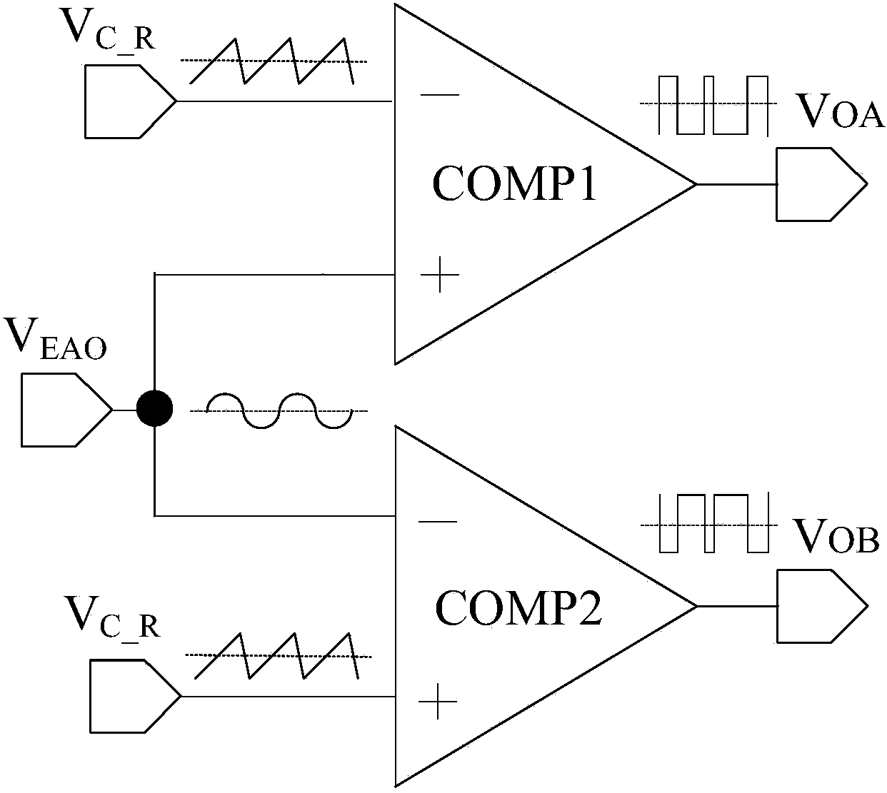
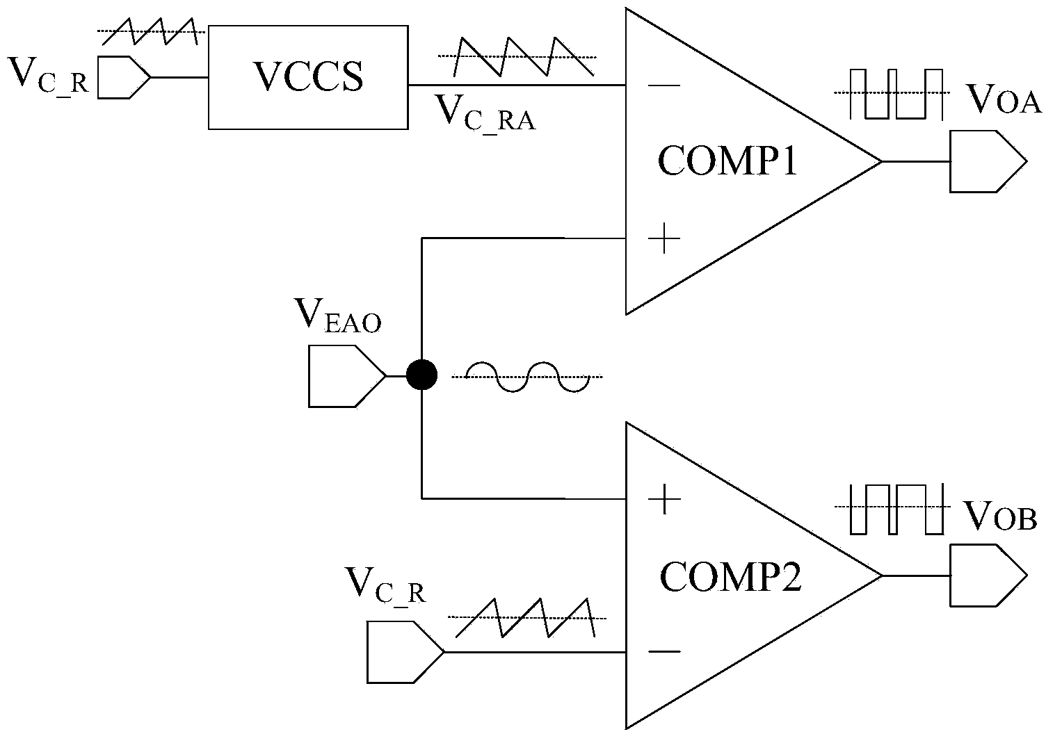
[0017] Such as figure 2 As shown, the pulse width modulation circuit of the present invention includes a voltage-controlled current source circuit VCCS, a first comparator COMP1 and a second comparator COMP2. Among them, the voltage-controlled current source circuit VCCS realizes the oscillator output voltage V C_R Shaping, through the voltage-controlled current source circuit VCCS to realize the V C_R Phase and amplitude modulation of the voltage, converting the oscillator output voltage to the input si...


PUM


Abstract

The invention relates to a pulse width modulation circuit which aims to solve the problem that a PWM circuit is poor in anti-interference performance in the prior art. According to the technical scheme, the pulse width modulation circuit comprises a first comparator, a second comparator and a voltage-controlled current source circuit, wherein the input end of the voltage-controlled current source circuit is connected with oscillator output voltage, the oscillator output voltage is converted into a signal complementary with an input signal and is input into one first input end of the first comparator, the other input end of the first comparator is connected with an error amplifier output signal, the output end of the first comparator outputs a first PWM signal, one input end of the second comparator is connected with the oscillator output voltage, the other input end of the second comparator is connected with the error amplifier output signal, and the output end of the second comparator outputs a second PWM signal. The required PWM signals are generated by means of triangular wave signals which are totally symmetric, occurrence of glitches is avoided, coupling interference is reduced, and precision of a sampling circuit and stability of a system are effectively improved.

Description

technical field [0001] The technical field of integrated circuits of the present invention particularly relates to a pulse width modulation (PWM) circuit. Background technique [0002] In electronic systems, PWM circuits often provide pulse modulation signals for the entire circuit system, adjust the duty cycle of pulses, and realize various circuit functions. It is an indispensable functional module. The traditional PWM circuit generally uses a comparator to output the oscillator output signal V C_R (typically a triangle wave) and the error amplifier output voltage V EAO A comparison is made to generate a square wave (PWM signal) with a duty cycle determined by the feedback signal. However, there is usually a coupling capacitance between the two signal lines of the PWM comparator in an electronic system, and the pulse transition on one signal line will damage the signal on the other signal line. Such a PWM comparator has low anti-interference ability. It causes glitches ...

Claims


Application Information

Patent Timeline
Patent Type & Authority Applications(China)
IPC IPC(8): H03K7/08
Inventor 周泽坤张庆岭张其营张瑜石跃明鑫王卓张波
Owner UNIV OF ELECTRONICS SCI & TECH OF CHINA
Why Eureka
Try Eureka