
Photocatalytic air purification device based on dispersive optical fiber

An air purification device and a technology of dispersing optical fibers, which are applied in the field of air purification, can solve the problems of low catalytic efficiency, secondary pollution, unavoidable direct electrical contact, inability to apply to closed, flammable and explosive environments, etc., to prevent secondary pollution, Avoid direct introduction and solve the effect of saturation failure

Inactive Publication Date: 2015-08-05
TIANJIN UNIV +1
View PDF6 Cites 0 Cited by
  • Summary
  • Abstract
  • Description
  • Claims
  • Application Information

AI Technical Summary

Problems solved by technology

Most of the existing photocatalytic reactors use ultraviolet lamps as the direct light source, and direct contact between electricity and heat and the working environment is inevitable. It is mainly aimed at indoor air and cannot be used in closed, flammable and explosive environments such as airplanes, subways, trains, and factories. environment, and cannot solve the problems of low catalytic efficiency and secondary pollution in the photocatalytic process

Method used


Image

  • Photocatalytic air purification device based on dispersive optical fiber
  • Photocatalytic air purification device based on dispersive optical fiber
  • Photocatalytic air purification device based on dispersive optical fiber

Examples


Embodiment Construction

[0041] The technical solutions of the present invention will be further described below in conjunction with specific embodiments.

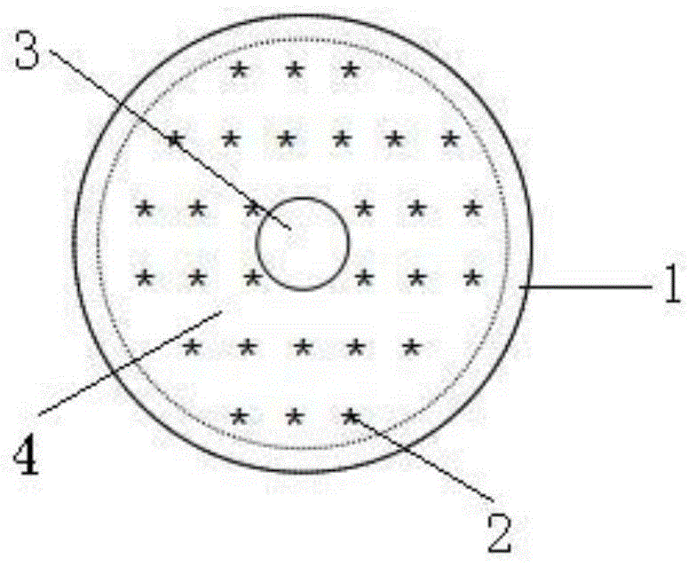
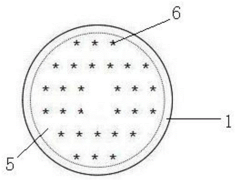
[0042] as attached figure 1 -Schematic diagram of the structure of the photocatalytic air purification device based on the dispersion optical fiber shown in 5, wherein 1 is the filter unit, 2 is the top mounting hole, 3 is the air outlet, 4 is the top cover, 5 is the bottom end cover, and 6 is the bottom installation Holes, 7 are diffused optical fibers, and 8 are activated carbon fibers.

[0043] The filter unit is a cylindrical filter unit HEPA, its radial cross-section is ring-shaped, and has a certain height, and its upper and lower ends are respectively connected with the top end cover and the bottom end cover.

[0044] There is an air outlet in the center of the top end cover, which is connected to the pump through a pipeline. When the pump as the air-inducing device is turned on, the air enters the air along the 360-degree side of the cyli...


PUM


Abstract

The invention discloses a photocatalytic air purification device based on diffused optical fibers, which comprises a filter unit and a photocatalytic unit, wherein the filter unit is a cylindrical one of which the radial cross section is shaped like a ring; the upper end and the lower end of the filter unit are respectively connected with a top end cover and a bottom end cover; the center of the top end cover is provided with an air outlet; top end mounting holes are uniformly arranged in the circumference of the air outlet; bottom end mounting holes are uniformly arranged in the bottom end cover; the photocatalytic unit is a fibrous catalytic unit; and one end of the photocatalytic unit is fixedly connected with the top end mounting holes, and the other end is fixedly connected with the bottom end mounting holes. According to the technical scheme of the invention, 360-degree lateral air intake is adopted, so that the secondary pollution influence caused by byproducts of photocatalytic reaction can be effectively decreased; and titanium dioxide is simultaneously loaded on surfaces of HEPA (high efficiency particulate air) and activated carbon fibers, thereby increasing the ultraviolet utilization ratio and effectively improving the air purification efficiency. Thus, the photocatalytic air purification device is applicable to closed, flammable and explosive environments such as aircrafts, subways, trains, factories and the like.

Description

technical field [0001] The invention belongs to the technical field of air purification, and more specifically relates to a photocatalytic air purification device for efficiently purifying harmful substances in the air by photocatalytic reaction. Background technique [0002] With the progress of global modernization and the continuous improvement of material and spiritual civilization, environmental pollution and ecological damage caused by industrialization have been widely valued by everyone. For this reason, experts at home and abroad have developed a variety of air purification devices to improve the surrounding living environment. At present, most of the air purification systems used at home and abroad use activated carbon adsorption technology, ozone purification technology, negative ion dust removal technology, high-voltage electrostatic technology and photocatalytic technology. In recent years, photocatalytic purification technology has been extensively researched ...

Claims


Application Information

Patent Timeline
Patent Type & Authority Patents(China)
IPC IPC(8): B01D53/86B01D46/24
CPCY02A50/2351
Inventor 霍爱群于涛商倩倩龚晨谭欣
Owner TIANJIN UNIV
Learn More