
Sand mold structure for integrally molded screw compressor case and manufacture and use method of sand mold structure

A screw compressor and casing technology, applied in the field of casting, can solve the problems of difficult processing, poor sealing, large overall length and size, etc., and achieve the effects of ensuring strength and sealing, short casing structure, and cost saving.

Active Publication Date: 2013-12-25
SUZHOU TORIN MACHINERY CASTING
View PDF6 Cites 24 Cited by
  • Summary
  • Abstract
  • Description
  • Claims
  • Application Information

AI Technical Summary

Problems solved by technology

The use of split structure has the following three disadvantages: 1. In terms of external dimensions: since the exhaust flange must be opened on the exhaust bearing seat, the overall length is large, resulting in waste of materials; 2. In terms of structural strength: the air compressor screw main engine The exhaust side is the final compressed gas with the highest pressure; bolt connection is used at this position, if the sealing of the surface is not good, it is easy to leak, and the strength requirements for the connecting bolts are relatively high; 3. Processing and assembly: split type The structure, the suction end and the exhaust end all need high-precision positioning pins to ensure the assembly accuracy of the rotor. Compared with the high processing accuracy requirements of each product, processing is difficult

Method used


Image

  • Sand mold structure for integrally molded screw compressor case and manufacture and use method of sand mold structure
  • Sand mold structure for integrally molded screw compressor case and manufacture and use method of sand mold structure
  • Sand mold structure for integrally molded screw compressor case and manufacture and use method of sand mold structure

Examples


Embodiment Construction

[0028] Below in conjunction with the embodiment shown in the accompanying drawings, the present invention is described in detail as follows:

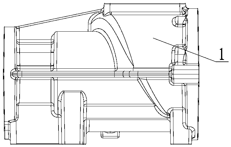
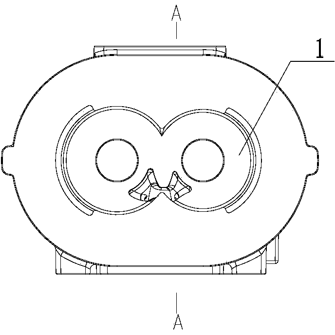
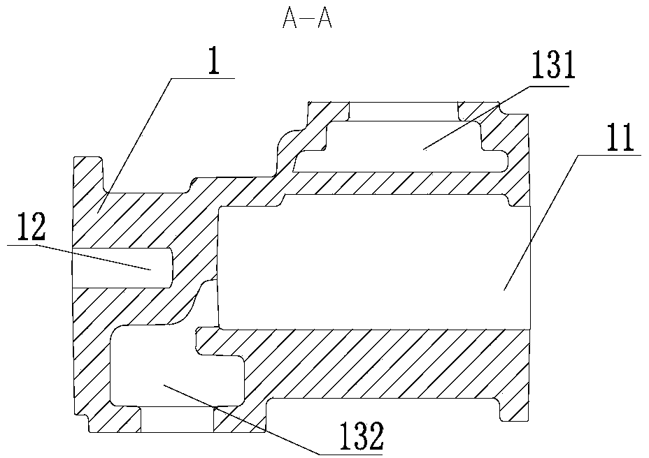
[0029] Such as figure 1 , 2 , 3, the main body of the casing 1 is columnar, and a large cavity 11 extending along its axis is opened inside it, and two cylindrical small cavity 11 is connected with the large cavity 11 and the axis is parallel to the axis of the large cavity 11. The cavity 12 is provided with two protrusions on its side wall, and the two protrusions are distributed on both sides of the large cavity and are respectively provided with medium-sized cavities, which are respectively the first medium-sized cavity 131 and the second medium-sized cavity 132 . Taking the axis of the large cavity 11 as the dividing line, when the large cavity 11 is placed horizontally, the first medium cavity 131 is located in the upper half of the casing 1, passing between the large cavity 11 and the small cavity 12 The communication holes are...


PUM


Abstract

The invention relates to a sand mold structure for an integrally molded screw compressor case. The sand mold structure comprises a lower sand mold, an upper sand mold, a second sand core and a first sand core, wherein the upper sand mold is provided with a plurality of air outlet holes for communicating a mold cavity with the outer part of the sand mold structure and a sprue for injecting molten iron. The invention also provides a manufacture and use method of the sand mold structure. The manufacture and use method comprises the following steps: modeling, manufacturing a core, milling a pouring cup and air holes, combining boxes, casting and cleaning. The sand mold structure and the manufacture and use method of the sand mold structure have the advantages that a bearing seat and a cast main body are integrally molded, so that the structure length of the case is short, the quantity of needed high-strength bolts is less and the cost is reduced; by means of castability of casting pieces, the strength and the sealability are guaranteed, and safe and reliable effects are achieved; the rotor assembling accuracy is guaranteed only by adopting a positioning pin for the air suctioning end, and a bearing hole and a rotor hole in the air exhausting end are machined by one step, so that high accuracy is guaranteed.

Description

[0001] technical field [0002] The invention relates to the field of casting, in particular to a sand mold structure integrally formed with a casing of a screw compressor and a manufacturing and using method thereof. [0003] Background technique [0004] At present, most of the domestic air compressor screw market adopts a split screw host structure, the main feature is that the exhaust bearing seat and the casing adopt a split structure. The use of split structure has the following three disadvantages: 1. In terms of external dimensions: since the exhaust flange must be opened on the exhaust bearing seat, the overall length is large, resulting in waste of materials; 2. In terms of structural strength: the air compressor screw main engine The exhaust side is the final compressed gas with the highest pressure; bolt connection is used at this position, if the sealing of the surface is not good, it is easy to leak, and the strength requirements for the connecting bolts are r...

Claims


Application Information

Patent Timeline
IPC IPC(8): B22C9/02B22C9/24
Inventor 王旸曹志华
Owner SUZHOU TORIN MACHINERY CASTING
Learn More