Novel electric welding machine

An electric welding machine, a new technology, applied in the direction of arc welding equipment, welding equipment, welding equipment, etc., can solve the problems of poor heat dissipation and waste of electric energy, and achieve the effect of simple structure, convenient use and reasonable design

Inactive Publication Date: 2013-12-25
NINGBO YINZHOU PINDA APPLIANCE SOLDER
View PDF7 Cites 7 Cited by
  • Summary
  • Abstract
  • Description
  • Claims
  • Application Information

AI Technical Summary

Problems solved by technology

At present, the heat dissipation method of the existing electric welding machine adopts the forced air cooling method to dissipate heat. The fan installation hole is opened on the rear side of the casing, and the cooling holes are opened on both sides of the casing, and each cooling hole is arranged in a vertical direction. The existing problem is: when the wind enters through the fan installation hole and then comes out through the heat dissipation hole for heat dissipation, it needs to overcome the natural wind flow resistance, the heat dissipation effect is not good, and the existing electric welding machine will always supply power no matter whether it is working or not, which will cause waste of electric energy

Method used


Image

  • Novel electric welding machine
  • Novel electric welding machine

Examples


Embodiment Construction

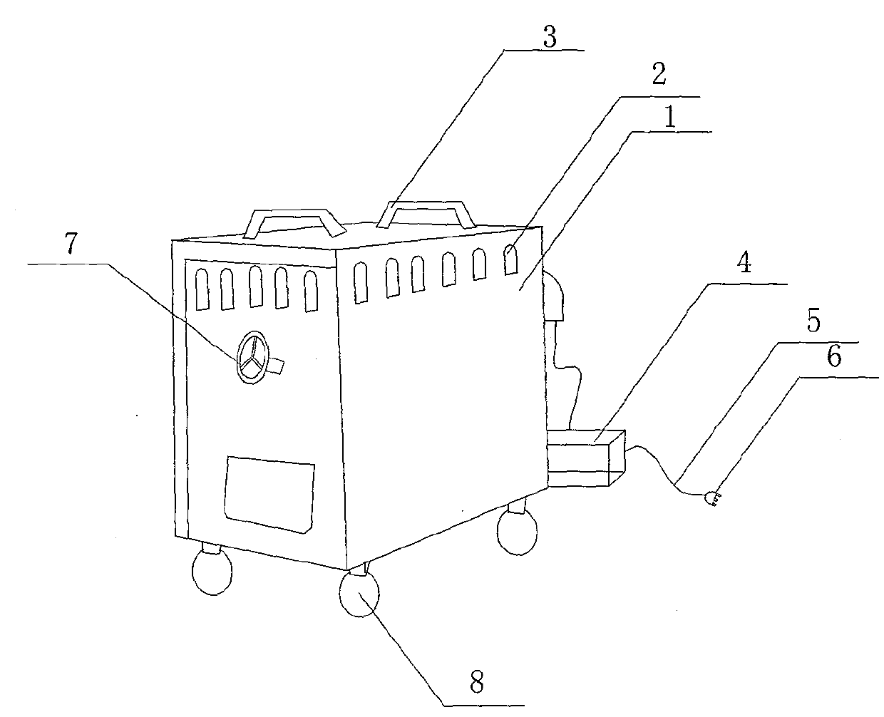
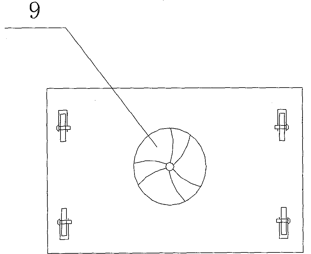
[0009] refer to Figure 1-2 , the specific embodiment adopts the following technical scheme: it comprises electric welding machine casing 1, cooling hole 2, handle 3, power saver protector 4, wire 5, plug 6, winding turntable 7, roller 8 and cooling fan 9, electric welding machine A handle 3 is arranged on the top of the casing 1, and several cooling holes 2 are evenly arranged on the outer wall around the upper end of the welding machine casing 1, and a power-saving protector 4 is connected to one side of the welding machine casing 1, and the power-saving protector 4 The wire 5 is connected to the plug 6, and the outer wall of the electric welding machine casing 1 is fixedly provided with a winding turntable 7, the bottom four feet of the electric welding machine casing 1 are provided with rollers 8, and the middle part of the bottom plate of the electric welding machine casing 1 is provided with A through hole, a cooling fan 9 is fixedly arranged below the through hole.

[...


PUM


Abstract

A novel electric welding machine relates to the technical field of electric welding machines. Handles are arranged on the top of an electric welding machine housing, moreover, a plurality of heat-dissipating holes are evenly formen in the four outer walls of the upper end of the electric welding machine housing, one side of the electric welding machine housing is connected with an electricity-saving protector, which is connected with a plug through a wire, furthermore, a winding handwheel is fixed on the outer wall of the electric welding machine housing, rollers are arranged on the four corners of the bottom of the electric welding machine housing, the middle of the bottom plate of the electric welding machine housing is provided with a through hole, and a cooling fan is fixed under the through hole. The structure of the novel electric welding machine is simple, and the design is reasonable; since the fan is arranged on the bottom, wind flow can upwardly dissipate out internal temperature via the heat-dissipating holes according to the natural wind flow law, so an optimal heat dissipation effect is achieved; moreover, since the electricity-saving protector is added, power can be automatically supplied when the novel electric welding machine operates, and can be cut off when the novel electric welding machine does not operate, and thereby electricity is saved; since the device for winding a welding wire is also arranged, the welding wire can be wound in order, and thereby the novel electric welding machine is more convenient to use.

Description

Technical field: [0001] The invention relates to the technical field of electric welding equipment, in particular to a novel electric welding machine. Background technique: [0002] The electric welding machine uses the high-temperature arc generated when the positive and negative poles are short-circuited instantaneously to melt the solder on the electrode and the material to be welded to achieve the purpose of combining them. Generally, electric welding machines can be divided into two types according to the type of output power supply, one is AC power supply; the other is DC power supply. It is made of the principle of inductance. The inductance will produce a huge voltage change when it is turned on and off. It uses the high-voltage arc generated when the positive and negative poles are short-circuited in an instant to melt the solder on the electrode to achieve their combination. the goal of. At present, the heat dissipation method of the existing electric welding mac...

Claims


Application Information

Patent Timeline
IPC IPC(8): B23K9/00B23K9/32B23K37/00
Inventor 蔡科彪
Owner NINGBO YINZHOU PINDA APPLIANCE SOLDER
Why Eureka
Try Eureka