Hydraulic braking system

A hydraulic brake and brake pump technology, applied in the direction of brakes, brake transmissions, transportation and packaging, etc., can solve problems such as weak braking, low reliability, and complicated braking systems, and achieve simplified and reliable structures. sex high effect

Inactive Publication Date: 2013-12-25
ZHENJIANG JINTIANCHEN NEW MATERIAL
View PDF5 Cites 4 Cited by
  • Summary
  • Abstract
  • Description
  • Claims
  • Application Information

AI Technical Summary

Problems solved by technology

[0002] A loader is an earthwork machine used to shovel and transport materials. The brake system of the loader is very important. If the brake system fails, serious accidents may occur. Currently, the brake system of the loader uses the brake system of air cap oil. , that is, use the air compressor to generate a certain pressure of compressed air and store it in the air tank, and control the connection of the pressure gas through the brake pedal. When the brake pedal is pressed, the pressure gas is i

Method used


Image

  • Hydraulic braking system

Examples


Embodiment Construction

[0011] Below in conjunction with accompanying drawing and embodiment the present invention will be further described:

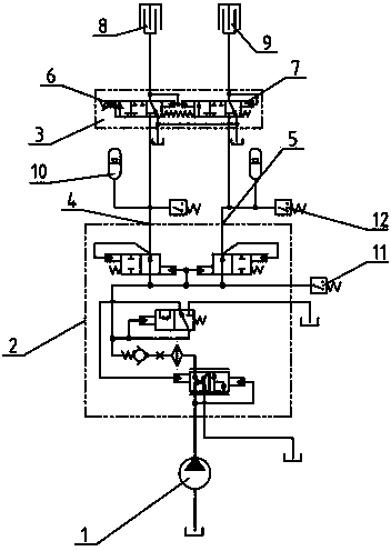
[0012] Such as figure 1 As shown, a hydraulic brake system includes a brake pump 1, a filling valve 2 and a pedal valve 3, the oil outlet of the brake pump 1 is connected to the oil inlet of the filling valve 2, and the The oil return port of the filling valve 2 is connected back to the oil tank, the filling valve 2 includes a first filling port 4 and a second filling port 5, and the pedal valve 3 includes a first pedal valve 6 and a second pedal valve 7. The first filling port 4 is connected to the oil inlet of the first pedal valve 6, the second filling port 5 is connected to the oil inlet of the second pedal valve 7, and the The oil return ports of the first pedal valve 6 and the second pedal valve 7 are all connected back to the oil tank, the oil outlet of the first pedal valve 6 is connected with the rear axle brake 8, and the oil outlet of the second p...


PUM


Abstract

The invention discloses a hydraulic braking system. The braking system comprises a braking pump, a prefill valve and a treadle valve, wherein the oil outlet of the braking pump is connected with the oil inlet of the prefill valve, the return opening of the prefill valve is connected with a return tank; the prefill valve comprises a first charging port and a second charging port; the treadle valve comprises a first treadle valve and a second treadle valve, wherein the first charging port is connected with the oil inlet of the first treadle valve, the second charging port is connected with the oil inlet of the second treadle valve, and the return openings of the first treadle valve and the second treadle valve are both connected with the return tank, the oil outlet of the first treadle valve is connected with a rear axle brake, and the oil outlet of the second treadle valve is connected with a front axle brake. By adopting the hydraulic braking system, the braking system can be greatly simplified in structure; by adopting two-way braking, the reliability is high.

Description

technical field [0001] The invention relates to a hydraulic braking system, in particular to a hydraulic braking system of a loader, and belongs to the technical field of engineering machinery. Background technique [0002] A loader is an earthwork machine used to shovel and transport materials. The brake system of the loader is very important. If the brake system fails, serious accidents may occur. Currently, the brake system of the loader uses the brake system of air cap oil. , that is, use the air compressor to generate a certain pressure of compressed air and store it in the air tank, and control the connection of the pressure gas through the brake pedal. When the brake pedal is pressed, the pressure gas is introduced into the system, and then the pressure gas passes through the afterburner. The brake oil is used to generate high-pressure brake oil by using the area difference, and the brake oil enters the brakes on the wheel side to generate braking force to brake. Howe...

Claims


Application Information

Patent Timeline
IPC IPC(8): B60T13/12
Inventor 陈建茗朱永琴刘万顺
Owner ZHENJIANG JINTIANCHEN NEW MATERIAL
Why Eureka
Try Eureka