A rail self-locking mine car anti-running device

A mine car and anti-running technology, which is applied in the direction of transportation and packaging, railway car body parts, brake components interacting with the track, etc., can solve the problems of limited practicality of the device, low degree of automation, difficulty, etc., and achieve prevention The effect of mine car sports car accident, low production cost and long service life

Active Publication Date: 2015-11-18
淮南市六信电控设备有限责任公司
View PDF14 Cites 0 Cited by
  • Summary
  • Abstract
  • Description
  • Claims
  • Application Information

AI Technical Summary

Problems solved by technology

[0003] In the aforementioned mechanical anti-sports car patented technology, the use of anti-vehicle claws, brake claws or backstop rods to realize the braking of the mine car may easily cause the mine car to overturn or derail, and due to the complex laying conditions of the track sleepers, it is easy to cause braking failure
Clamping or holding rail brake devices are relatively safe and reliable, but the existing technology mostly uses overspeed detection to control the start of the brake device. The structure of the device is relatively complicated, and the key technology is the setting of the critical speed. Large, the braking kinetic energy of the mine car must be large, and the braking effect is difficult to guarantee. If the setting is too small, it is easy to cause false start of the braking device. It is difficult to set the critical overspeed value, which greatly limits the practicability of this type of device.
However, the anti-running device of the mine car brake is realized by controlling the brake shaft gripper through the handle, which has a low degree of automation and is not suitable for automatic anti-running during the operation of the mine car.

Method used


Image

  • A rail self-locking mine car anti-running device
  • A rail self-locking mine car anti-running device
  • A rail self-locking mine car anti-running device

Examples


Embodiment Construction

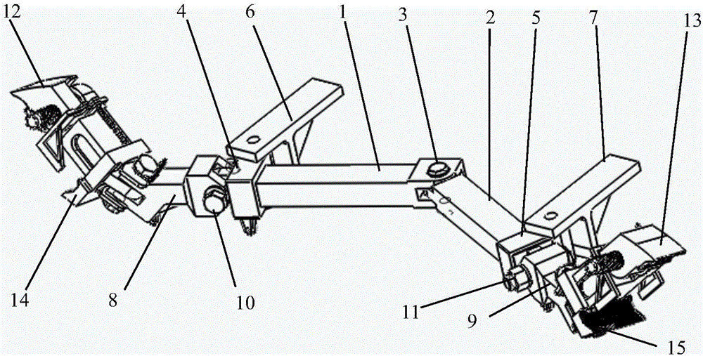
[0036] The present invention will be described in further detail below in conjunction with the accompanying drawings and specific embodiments.

[0037] like figure 1 As shown, the rail self-locking mine car anti-running device of the present invention includes a left brake rocker arm 1, a right brake rocker arm 2, a brake rocker arm hinge shaft 3, a left rocker arm sliding sleeve 4, and a right rocker arm sliding sleeve 5 , left fixed angle iron 6, right fixed angle iron 7, left brake pawl connection block 8, right brake pawl connection block 9, left brake pawl connection block pin 10, right brake pawl connection block pin 11, left Brake outer claw 12, right brake outer claw 13, left brake inner claw 14 and right brake inner claw 15. Among them, the left brake rocker arm 1 and the right brake rocker arm 2 are connected by the brake rocker hinge shaft 3, and the hinge angle can be changed horizontally, sliding in the left rocker arm sliding sleeve 4 and the right rocker arm sl...


PUM


Abstract

The invention discloses a rail clamping self-locking type anti-running device for a mine vehicle. The device comprises a left braking rocker arm, a right braking rocker arm, left fixed angle iron, right fixed angle iron, a braking rocker arm hinge shaft, a left rocker arm sliding sleeve, a right rocker arm sliding sleeve, a left braking claw connecting block, a right braking claw connecting block, a left braking claw connecting block pin shaft, a right braking claw connecting block pin shaft, a left braking claw truss, a right braking claw truss, a left braking inner claw, a left braking outer claw, a right braking inner claw, a right braking outer claw, a left suspension rope, a right suspension rope, a left braking rope and a right braking rope. According to the device, a mechanical structure is adopted, so that the device is simple in structure, convenient to implement, low in manufacturing cost, easy to maintain and long in service life; a rocker arm mechanism self-locking principle is utilized, and the mine vehicle is braked in a rail clamping way, so that the risks of turnover, derailment, braking failures, secondary damage and the like are eliminated, and running accidents of the mine vehicle can be effectively prevented.

Description

technical field [0001] The invention relates to mine auxiliary transportation equipment, in particular to an anti-running device for underground auxiliary transportation mine cars in coal mines. Background technique [0002] Sports car accidents account for a considerable proportion of auxiliary transportation accidents in coal mines. Once a sports car accident occurs, it often causes heavy losses of life and property. Therefore, preventing sports cars has always been one of the key tasks in coal mine safety production management. The "Coal Mine Safety Regulations" issued by the State Coal Mine Safety Supervision Bureau in 2009 clearly stipulates the car stop and anti-running device in the inclined roadway, and requires that the inclined shaft must be equipped with "one slope and three stops" anti-running device. At present, the anti-sports car device has a history of more than ten years in China, and there are various types. The more common ones are manual type, impact type...

Claims


Application Information

Patent Timeline
Patent Type & Authority Patents(China)
IPC IPC(8): B61H7/12
Inventor 陈清华靳华伟李永梅董长帅袁力吴亮徐曼曼庞立杨新春
Owner 淮南市六信电控设备有限责任公司
Why Eureka
Try Eureka