Pump cap screwing machine

A technology of capping machine and pump cap, applied in the direction of threaded bottle caps, etc., can solve the problem that the capping work of the straw type pump cap cannot be realized, the lifting of the straw type pump cap straw and the accurate insertion of the bottom of the bottle and the direction of the mouth of the cap can be solved. Consistency and other problems, to achieve the effects of easy maintenance, adjustable cap tightening force, and easy connection

Active Publication Date: 2015-03-18
CHANGZHOU HUITUO TECH
View PDF6 Cites 3 Cited by
  • Summary
  • Abstract
  • Description
  • Claims
  • Application Information

AI Technical Summary

Problems solved by technology

However, the existing technology cannot meet the requirements of ensuring that one bottle corresponds to one cap when feeding caps during the capping process, and cannot realize the function of lifting the suction tube of the suction tube pump cap and accurately inserting the bottom of the bottle, and requires that the production process be beautiful and easy to install. To carry out the first process, it is necessary to straighten out the mouth of the bottle of the spray pump so that the mouth of the bottle cap is in the same direction, but the existing technology cannot solve the problem of the same direction of the mouth of the bottle cap, and there is no smart pump that can intelligently screw the pump cap. The capping machine cannot realize the capping work of straw pump caps, duckbill caps, spray gun caps and other bottles

Method used


Image

  • Pump cap screwing machine
  • Pump cap screwing machine
  • Pump cap screwing machine

Examples


Embodiment Construction

[0044] In order to make the content of the present invention easier to understand clearly, the present invention will be described in further detail below according to specific embodiments in conjunction with the accompanying drawings,

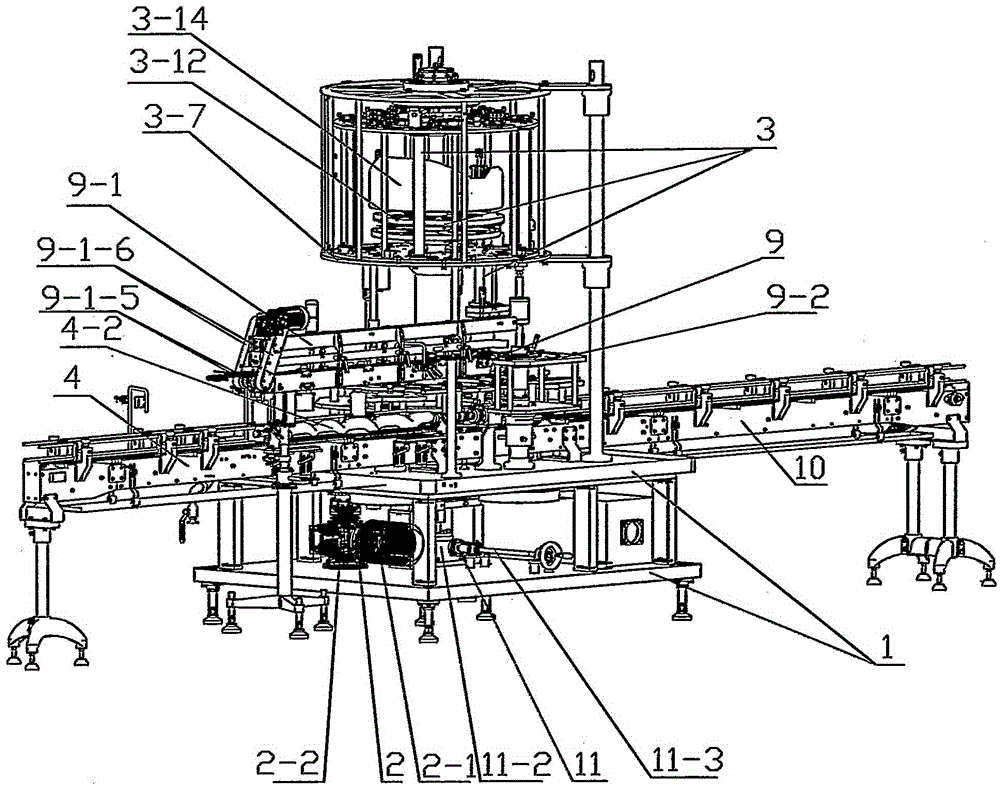
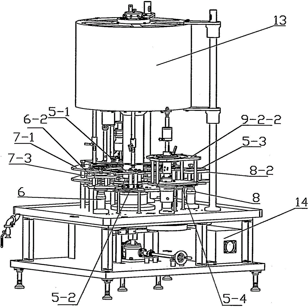
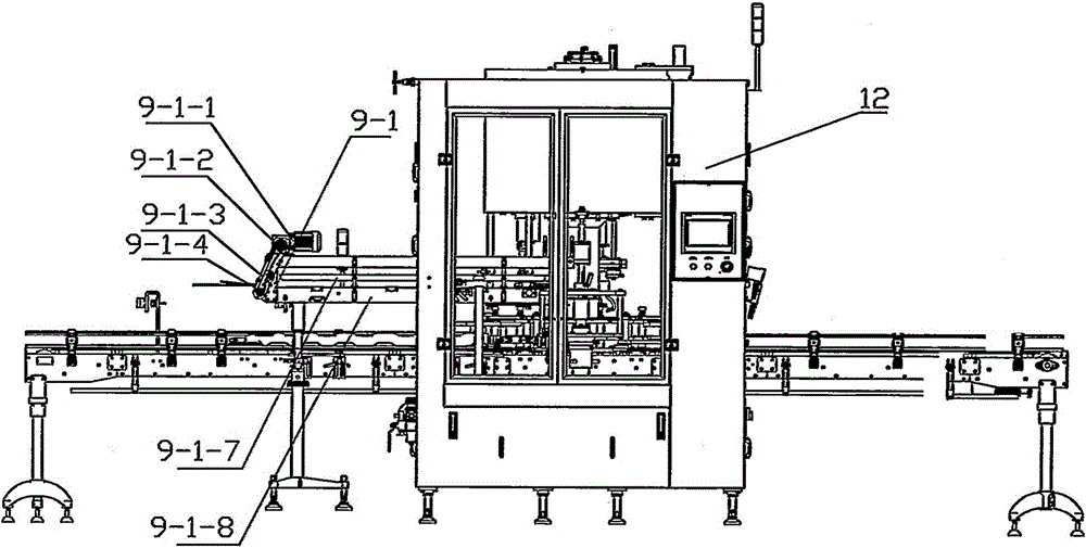
[0045] Such as Figure 1~15 As shown, a pump cap screwing machine includes a frame 1, a power transmission device 2, a screw cap assembly 3, a bottle body supply device 4, a first bottle guide device 5, a second bottle guide device 15, a bottle feeding device Star wheel device 6, bottle retaining device 7, bottle output star wheel device 8, cap supply device 9 and bottle output device 10, wherein:

[0046] A. The bottle supply device 4 includes a screw 4-2, a cardan shaft coupling 4-3, a screw drive power part 4-4 and a bottle conveyor belt 4-1 for conveying the bottle, and a screw drive power part 4-4 The screw rod 4-2 is connected with the screw rod 4-2 through the cardan shaft coupling 4-3, the screw rod 4-2 is arranged on the side above t...


PUM


Abstract

The invention discloses a pump cap screwing machine, which comprises a rack, a power transmission device, a cap screwing assembly, a bottle body supply device, a first bottle guide device, a second bottle guide device, a bottle feed star wheel device, a bottle stopping device, a bottle discharge star wheel device, a cap supply device, a rotating air path distribution device and a bottle output device, wherein the first bottle guide device is arranged at the tail of a screw rod and is matched with the bottle feed star wheel device, and a bottle feed inlet is formed between the first bottle guide device and the bottle feed star wheel device; the bottle feed star wheel device comprises a bottle feed turntable and a bottle feed rotating shaft which is movably connected with the power transmission device, the bottle feed turntable is provided with bottle feed clamping mounts and the bottle feed turntable is sheathed on the bottle feed rotating shaft; the second bottle guide device is matched with the bottle discharge star wheel device, a bottle discharge outlet is formed between the second bottle guide device and the bottle discharge star wheel device and the bottle stopping device is connected with the bottle discharge outlet. The pump cap screwing machine has the advantages that the structure is simple, the production efficiency is high, the processes of cap conveying, cap grabbing and cap screwing can be finished in one step, the effect of multiple products on one production line can be realized and the cap screwing effect is good.

Description

technical field [0001] The invention relates to a pump cover screwing machine, which belongs to the technical field of packaging machinery. Background technique [0002] At present, in the daily chemical, food, pharmaceutical and other industries, the pump cap screwing machine is a device that can screw the bottle cap on the bottle body. The pump cap screwing machine generally includes a frame, a power transmission device and a capping assembly. As a result, there is a rotating part in the screw cap assembly, the power device drives the rotating part to rotate, the bottle cap is stuck in the chuck of the rotating part, and with the rotation of the rotating part, the bottle cap is screwed tightly on the bottle body. However, the existing technology cannot meet the requirements of ensuring that one bottle corresponds to one cap when feeding caps during the capping process, and cannot realize the function of lifting the suction tube of the suction tube pump cap and accurately i...

Claims


Application Information

Patent Timeline
Patent Type & Authority Patents(China)
IPC IPC(8): B67B3/20
Inventor 段学连胡家鑫
Owner CHANGZHOU HUITUO TECH
Why Eureka
Try Eureka