
Lens X, Y, theta Z three-freedom-degree micro-moving adjusting device

A technology for adjusting devices and degrees of freedom, applied in installation, optics, instruments, etc., can solve the problems of high processing cost and difficult processing technology, and achieve the effect of reducing processing cost, reducing processing technology difficulty, and avoiding local damage

Inactive Publication Date: 2013-12-25
CHANGCHUN INST OF OPTICS FINE MECHANICS & PHYSICS CHINESE ACAD OF SCI
View PDF7 Cites 7 Cited by
  • Summary
  • Abstract
  • Description
  • Claims
  • Application Information

AI Technical Summary

Problems solved by technology

[0005] The present invention is to solve prior art optical element X, Y, θ Z The processing technology of the three-degree-of-freedom micro-adjustment device is difficult and the processing cost is high. A lens flexible micro-adjustment device based on three circumferentially uniformly distributed folding hinges is proposed.

Method used


Image

  • Lens X, Y, theta Z three-freedom-degree micro-moving adjusting device
  • Lens X, Y, theta Z three-freedom-degree micro-moving adjusting device
  • Lens X, Y, theta Z three-freedom-degree micro-moving adjusting device

Examples


Embodiment Construction

[0011] The present invention will be described in further detail below in conjunction with the accompanying drawings.

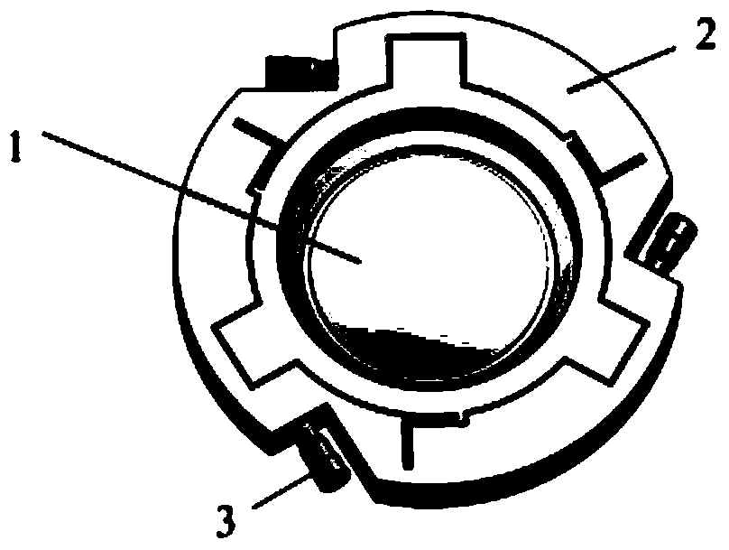
[0012] Such as figure 1 Shown, lens X, Y, θ Z The three-degree-of-freedom micro-adjustment device includes a lens 1 , a frame 2 and three drivers 3 , the lens 1 and the frame 2 are connected by glue, and the three drivers 3 are fixed on the frame 2 .

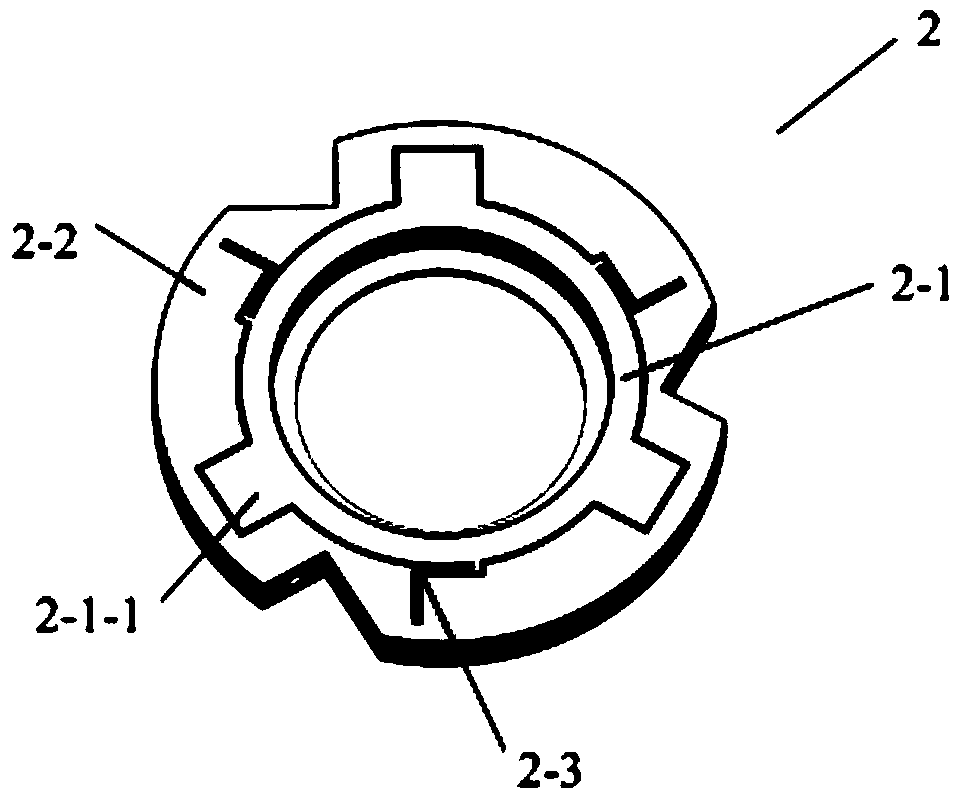
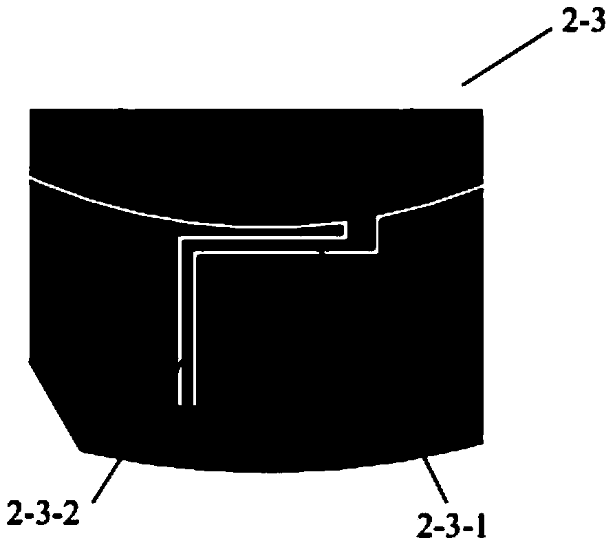
[0013] Such as figure 2 As shown, the picture frame 2 is an integrated structure composed of a picture frame inner ring 2-1, a picture frame outer ring 2-2 and three circumferentially uniform folding hinges 2-3. And other methods of processing. The lens 1 is connected to the inner ring 2-1 of the mirror frame by means of glue. The three drivers 3 are fixed on the outer ring 2-2 of the mirror frame, and the input displacement acts on the corresponding driver applying blocks 2-1-1, and the three driver applying blocks 2-1-1 are evenly distributed in the circumferential direction On the inner ring 2-1 of the...


PUM


Abstract

The invention discloses a lens X, Y, theta Z three-freedom-degree micro-moving adjusting device, belongs to the field of lithography objective structure designs and aberration compensation, and aims at solving the problems that an optical element X, Y, theta Z three-freedom-degree micro-moving adjusting device in the prior art is large in processing technology difficulty and high in processing cost. The device comprises a lens, a lens frame and three drivers. The lens is connected with the lens frame in an adhesion mode. The three drivers are fixed on the lens frame. The device is characterized in that the lens frame is of an integrated structure composed of a lens frame inner ring, a lens frame outer ring and three folding hinges which are evenly distributed in the circumferential direction, three driver force applying blocks are evenly distributed in the circumferential direction on the lens frame inner ring, the lens is connected with the lens frame inner ring in an adhesion mode, the three drivers are fixed on the lens frame outer ring, action of input displacement of the drivers is applied on corresponding driver force applying blocks, each folding hinge is composed of a tangential elastic piece and a radial elastic piece, the tangential elastic pieces are connected with the lens frame inner ring, and the radial elastic pieces are connected with the lens frame outer ring.

Description

technical field [0001] The invention belongs to the field of structure design and aberration compensation of deep ultraviolet projection lithography objective lens, and relates to a lens X, Y, θ that can be used in a lithography projection objective lens system Z Three-degree-of-freedom adjustment micro-motion device. Background technique [0002] Projection lithography equipment is the key equipment in the manufacturing process of large-scale integrated circuits. In recent years, with the continuous improvement of the fineness of the line width of integrated circuits, the resolution of projection optical equipment has gradually improved. At present, the ArF excimer laser with a wavelength of 193.368nm Lithography equipment has become the mainstream equipment for integrated circuit manufacturing at 90nm, 65nm and 45nm nodes. [0003] During the adjustment and use of the projection lithography objective lens, in order to meet the good optical performance of the objective len...

Claims


Application Information

Patent Timeline
Patent Type & Authority Applications(China)
IPC IPC(8): G02B7/02
Inventor 赵磊杨怀江隋永新张德福
Owner CHANGCHUN INST OF OPTICS FINE MECHANICS & PHYSICS CHINESE ACAD OF SCI
Learn More