
Household energy management system

An energy management system and home appliance management technology, applied in the direction of electrical program control, comprehensive factory control, etc., can solve the problems of less research by residents and users, and achieve the goal of improving initiative and freedom, reducing impact, and low power consumption Effect

Inactive Publication Date: 2013-12-25
苏州市思玛特电力科技有限公司
View PDF5 Cites 7 Cited by
  • Summary
  • Abstract
  • Description
  • Claims
  • Application Information

AI Technical Summary

Problems solved by technology

At present, most of the research on incentive DR control focuses on some large power users, such as industrial and commercial users, but less research on residential users

Method used


Image

  • Household energy management system
  • Household energy management system
  • Household energy management system

Examples


Embodiment Construction

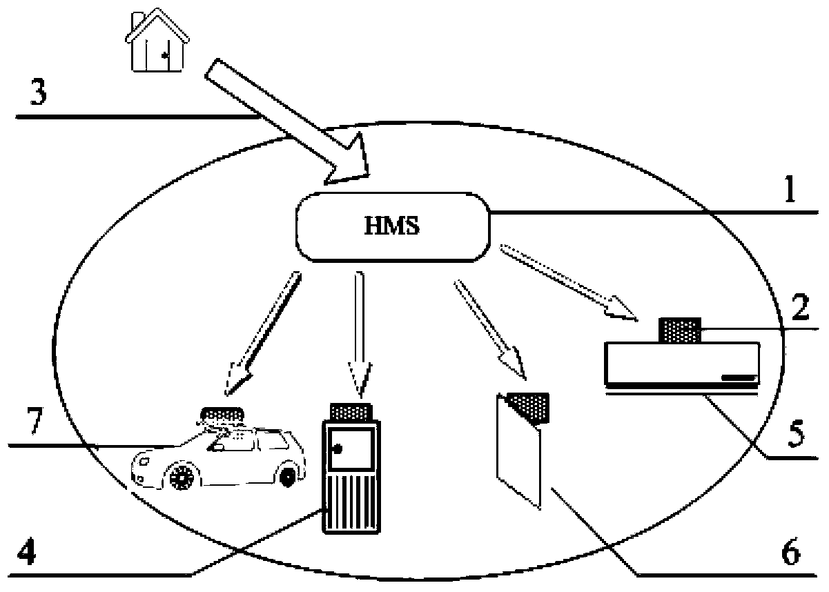
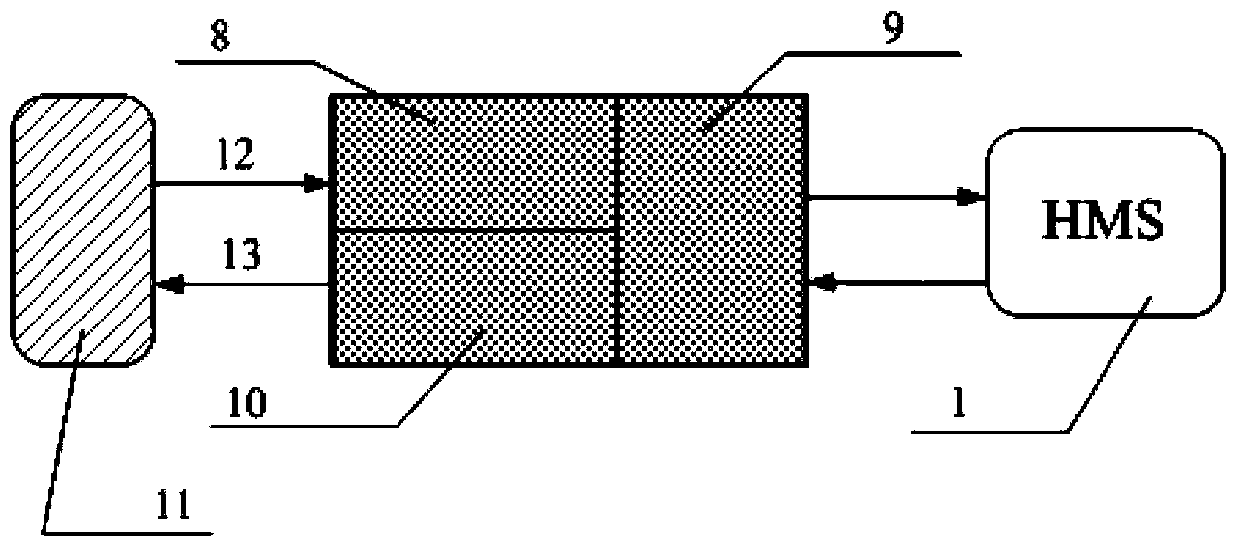
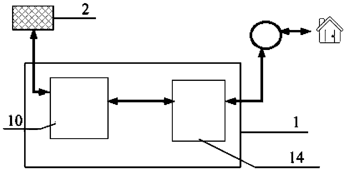
[0023] Such as figure 1 , figure 2 with image 3 As shown, a home energy management (HEM) system of the present invention includes two parts: a home appliance management control system (HMS) 1 and a home appliance interface unit 2 . The home appliance management and control system (HMS) 1 is the management and decision-making control unit for all high-power electrical appliances in the home, including a PC or processor 14 that runs corresponding control algorithms. Between the high-power household appliance load 11 and the household appliance management and control system 1 , a household appliance interface (interface) unit 2 is also provided in order to realize demand-side response management. The home appliance interface unit 2 includes a data collection and processing module 8, a communication module 9, and a control module 10, etc., which can realize power data collection of high-power home appliances, communication with HMS, and state control of local loads 11, etc.

...


PUM


Abstract

The invention discloses a household energy management system. The household energy management system comprises a household appliance management control system (1). The household appliance management control system (1) is a management and decision control unit for all high-power household appliances in a family and comprises a PC or a processer (14) operating corresponding control algorithms. In order to achieve demand-side response management, a household appliance interface unit (2) is further arranged between a high-power household appliance load (11) and the household appliance management control system (1), so that power data collection of the high-power household appliances, communication between the high-power household appliances and the household appliance management control system, and control over the local load state are achieved. According to the household energy management system, mainly, DR control over the medium-power and high-power household appliance load of a resident user is conducted, and on the premise that the comfort degree of the user and the load priority are fully considered, full automation of control is achieved.

Description

technical field [0001] The invention relates to a management system, in particular to a family energy management system. Background technique [0002] In order to meet the demand for electricity, the early electric power sector generally determined the power generation capacity according to the forecasted power load, so that the power generation capacity could meet the demand level. Although this approach can ensure the demand for electricity during peak hours, it leaves some generating capacity idle during periods other than peak load. Around the 1970s, the oil crisis led to a sharp rise in energy prices. Western countries no longer blindly pursued the practice of meeting demand with installed capacity, and launched explorations and practices to solve the contradiction between power supply and demand by reducing demand-side loads. Demand-side response The concept of (demand response, DR) was born. [0003] According to different incentive methods, DR can be divided into t...

Claims


Application Information

Patent Timeline
Patent Type & Authority Applications(China)
IPC IPC(8): G05B19/418
Inventor 汤奕塞弗瑞海姆
Owner 苏州市思玛特电力科技有限公司
Learn More