Eureka AIR delivers breakthrough ideas for toughest innovation challenges, trusted by R&D personnel around the world.

Control transformer

A technology of transformers and magnetic cores, applied in the field of transformers, can solve the problems of increasing the perimeter and total length of copper wire turns, increasing heat consumption of DC resistance, and unbalanced magnetic field distribution, so as to improve electromagnetic conversion efficiency and shorten the cycle time. The effect of long and saving copper consumption

Inactive Publication Date: 2013-12-25
NINGBO AUPUL TELECOMM EQUIP +1
View PDF4 Cites 2 Cited by
  • Summary
  • Abstract
  • Description
  • Claims
  • Application Information

AI Technical Summary

Problems solved by technology

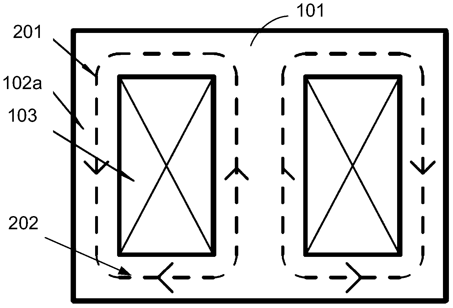
[0003] At present, most of the control transformer products produced in the domestic and foreign markets adopt the "EI" type lamination mode. The main disadvantage is that the magnetic force lines generated by the coil are in a free state at both ends of the transformer, the magnetic field distribution is unbalanced, and the electromagnetic efficiency is low.
In order to achieve the purpose of reducing the magnetic flux density and thereby reducing the magnetic loss, traditional products adopt the method of increasing the thickness of the iron chip and increasing the cross-sectional area of ​​the iron core, but this increases the circumference and total length of the turns of the wire-wrapped copper wire, so The problem of increasing the amount of copper used and increasing the heat loss of the DC resistance

Method used


Image

  • Control transformer
  • Control transformer
  • Control transformer

Examples


Embodiment Construction

[0022] According to Faraday's law of electromagnetic induction V=-N(dФ / dt)=-NBAω, the invented control transformer is explained. In the formula, V is the generated voltage, N is the number of turns of the coil, dФ / dt is the changing magnetic field, B is the strength of the magnetic field, and A is the cross-sectional area of ​​the magnetic core, so that the voltage V and the magnetic field strength B are the magnetic core cross-sectional area A The product is proportional to the voltage and the number of turns of the coil. In the case of a set primary or secondary voltage, the product of the number of turns of the coil and the cross-sectional area of ​​the magnetic core is a design constant. The greater the magnetic field strength, the The larger the generated voltage (or current), the larger the cross-sectional area of ​​the magnetic core, the larger the generated voltage (or current), and the higher the electromagnetic conversion efficiency.

[0023] Embodiments of the prese...


PUM


Abstract

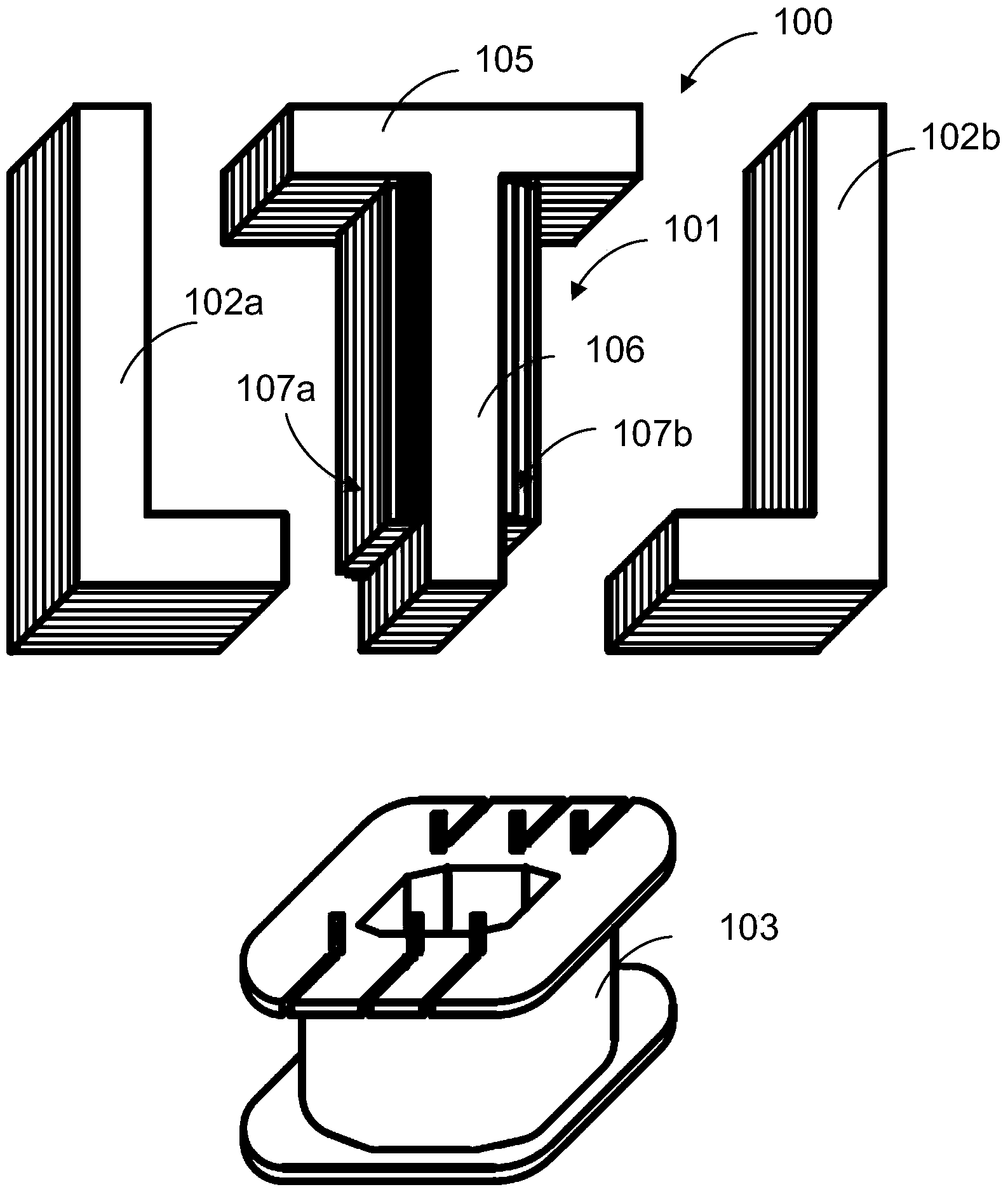
The invention discloses a control transformer. The control transformer mainly comprises a main magnetic core, a plurality of auxiliary magnetic cores and a pair of magnet yokes, wherein the main magnetic core is a T-shaped magnetic core column which is composed of a top portion and a column body, the auxiliary magnetic cores are attached to the main magnetic core to form a multiple-step stair structure, and the magnet yokes are arranged on the two sides of the main magnetic core respectively, so that an integral magnetic path structure is formed by the magnet yokes, the main magnetic core and the auxiliary magnetic cores. When the control transformer is used, unbonded magnetic force lines on the two end faces of the magnetic core column can be fully used and be fully absorbed, electromagnetic conversion efficiency of the control transformer is improved, power consumption of the control transformer can be reduced, copper consumption is reduced, and the manufacturing cost of the control transformer is reduced.

Description

technical field [0001] The invention relates to the field of transformers, in particular to BK and JBK series control transformers. Background technique [0002] Control transformers are widely used in various places. BK, JBK series control transformers can generally be used as power sources for controlling work lighting and signal lamps in machine tools and mechanical equipment, and can also be used as power sources. [0003] At present, most of the control transformer products produced in the domestic and foreign markets adopt the "EI" type lamination mode. The main disadvantage is that the magnetic field lines generated by the coil are in a free state at both ends of the transformer, the magnetic field distribution is unbalanced, and the electromagnetic efficiency is low. In order to achieve the purpose of reducing the magnetic flux density and thereby reducing the magnetic loss, traditional products adopt the method of increasing the thickness of the iron chip and incre...

Claims


Application Information

Patent Timeline
Patent Type & Authority Applications(China)
IPC IPC(8): H01F27/24H01F27/26
Inventor 周尧达张乃铫
Owner NINGBO AUPUL TELECOMM EQUIP
Why Eureka
Eureka Blog
Learn More