Energy storage system by using electromagnetic transforming

An electromagnetic and electromagnetic induction technology, applied in the field of energy storage charging devices, can solve problems such as incompatibility, limited use of electrical appliances, and different specifications, to prevent mutual interference or cancellation of magnetic fields, improve electromagnetic conversion efficiency, and improve transmission efficiency. Effect

Inactive Publication Date: 2017-10-10
肖斌
View PDF0 Cites 0 Cited by
  • Summary
  • Abstract
  • Description
  • Claims
  • Application Information

AI Technical Summary

Problems solved by technology

It has the problem of electricity safety, and there are also disadvantages such as poor electrode contact, many charger models and different specifications, which cannot be used universally, and the use of electrical appliances is restricted due to wire involvement during charging, etc.

Method used


Image

  • Energy storage system by using electromagnetic transforming
  • Energy storage system by using electromagnetic transforming

Examples


Embodiment 1

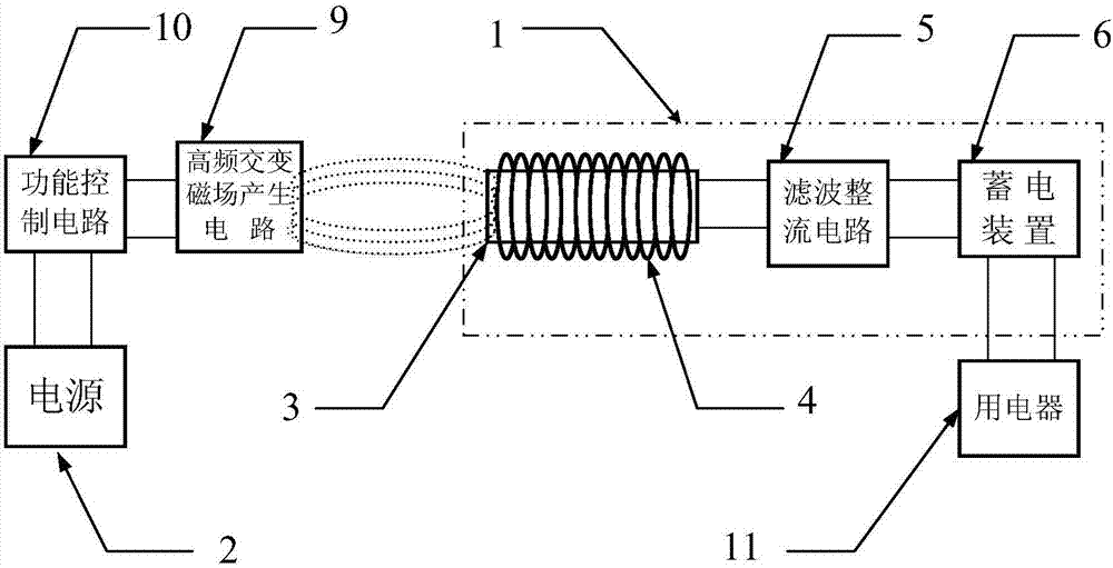
[0018] The power source 2 of the electromagnetic conversion energy storage system can be alternating current or direct current, such as a battery. If the DC power supply is used, the high-frequency alternating magnetic field generating circuit 9 includes a high-frequency push-pull oscillation circuit. The high-frequency alternating magnetic field generating circuit 9 generally includes a coil, a resonance circuit, an amplifier circuit, and a function control circuit 10 including a control circuit, an overcurrent detection circuit, and a feedback circuit.

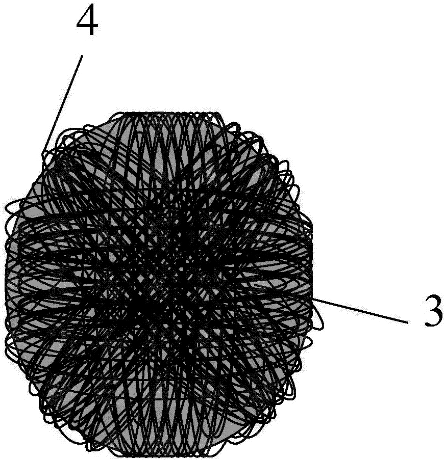
[0019] The isotropic electromagnetic induction energy storage device 1 includes a magnet 3 , a high-frequency coil 4 , a filter rectifier circuit 5 , and a power storage device 6 . The magnets are generally in the form of cylinders, but may also be prismatic. The magnets are made of materials with low hysteresis, such as magnets, cobalt or nickel. The magnets are two perpendicular to each other, or three perpendicular to e...

Embodiment 2

[0024] The electromagnetic conversion energy storage system is connected to the medical device placed in the human body. The medical devices placed in the human body include but are not limited to pacemakers, charge-coupled assemblies, artificial organs, electronic capsule endoscopes, and the like. These medical devices are widely used in clinical practice. At present, the energy of these medical devices can only be powered by wires outside the body or self-powered by batteries inside the body, causing great inconvenience to patients.

[0025] Applying the electromagnetic conversion energy storage system of the present invention, the high-frequency alternating magnetic field generating circuit 9 is placed outside the human body, and the electrical appliance 11 ie the medical device together with the homogeneous electromagnetic induction energy storage device 1 and the power storage device 6 are placed in the human body. The high-frequency alternating magnetic field generating...


PUM


Abstract

The invention relates to an electromagnetic conversion energy storage system, which includes a homogeneous electromagnetic induction energy storage device and a high-frequency alternating magnetic field generating circuit. The alternating magnetic field generating circuit is driven by a power supply to generate a high-frequency alternating magnetic field, and when the homogeneous electromagnetic induction energy storage device approaches, a current is generated under the action of electromagnetic induction. The isotropic electromagnetic induction energy storage device further includes a magnet, a high-frequency coil, a filter rectifier circuit, and an electric storage device. The magnets are two or three and each is perpendicular to each other. The high-frequency coils are divided into two or three groups to wind the magnets. . The invention has the design of the uniformity of the magnetic field acceptance, which minimizes the dead angle of the magnetic field acceptance direction, thereby improving the coupling coefficient and the electromagnetic conversion efficiency. The invention is applicable to various electric appliances, especially for electric appliances such as medical devices in the human body, which are difficult to be implemented by traditional contact charging.

Description

technical field [0001] The invention relates to an energy storage charging device, in particular to an energy storage charging device applying electromagnetic induction. Background technique [0002] In this age of electrification, the use of rechargeable batteries has become quite widespread. The traditional charging and energy storage technology for rechargeable batteries is realized by directly contacting the positive and negative poles of the power supply with the rechargeable battery. This charging technology is still widely used today. It has problems of electricity safety, poor electrode contact, many types of chargers, different specifications, which cannot be used universally, and the use of electrical appliances is restricted due to the involvement of wires during charging. SUMMARY OF THE INVENTION [0003] The purpose of the present invention is to avoid the deficiencies in the prior art and provide an electromagnetic conversion energy storage system. [0004...

Claims


Application Information

Patent Timeline
Patent Type & Authority Applications(China)
IPC IPC(8): H02J7/00H02J50/10H02J50/12H01F27/30
CPCH02J7/025H01F27/306
Inventor 肖斌
Owner 肖斌
Why Eureka
Try Eureka