
Coaxial stripping device

A stripping device, coaxial cable technology, applied in circuit/collector parts, equipment for dismantling/armored cables, electrical components, etc., can solve the problems of bulky, low stripping efficiency, etc. The effect of damage to the wire and low production cost

Active Publication Date: 2015-08-26
GOERTEK INC
View PDF5 Cites 0 Cited by
  • Summary
  • Abstract
  • Description
  • Claims
  • Application Information

AI Technical Summary

Problems solved by technology

[0003] The technical problem to be solved by the present invention is to provide a coaxial stripping device to solve the technical problems of the traditional coaxial stripping device, which are bulky and have low stripping efficiency

Method used


Image

  • Coaxial stripping device
  • Coaxial stripping device
  • Coaxial stripping device

Examples


Embodiment Construction

[0024] The present invention will be further described below in conjunction with the accompanying drawings and embodiments.

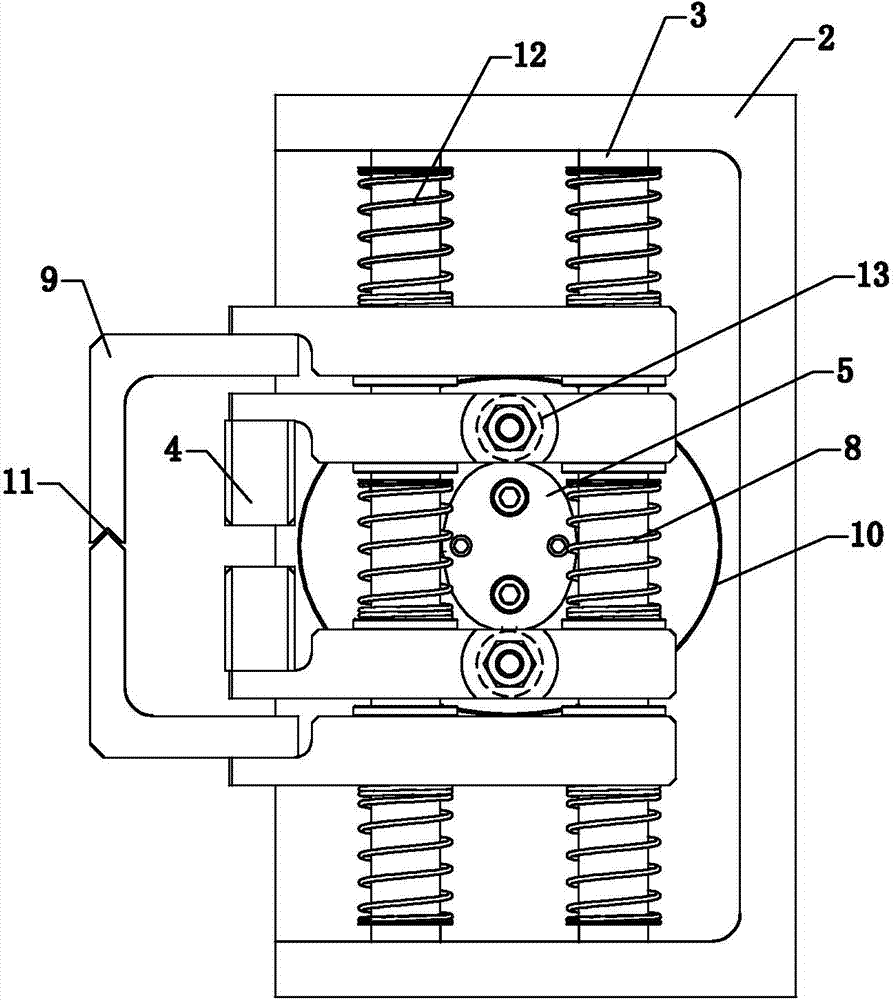
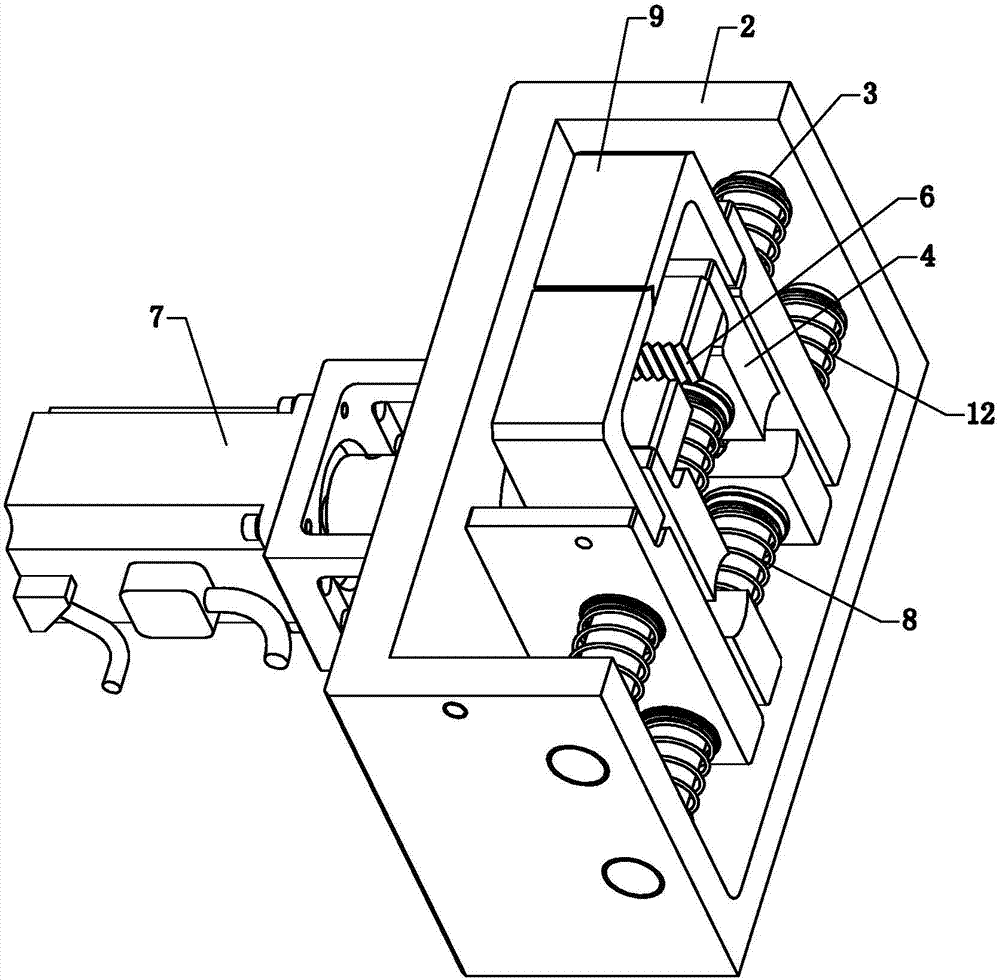
[0025] Such as figure 1 , figure 2 and image 3 Commonly shown, the coaxial cable stripping device includes a frame 1, a positioning tool 14 for arranging and fixing the coaxial cable and a pulling mechanism for pulling the coaxial cable cladding are installed on the frame 1, The drawing mechanism includes: a mounting seat 2 which is slidably installed on the frame 1 and driven by a driving device; There are two paired jaw monomers 4 that are slidably installed, and a first cam mechanism that is driven by a first power device to open and close the jaw monomers 4 is arranged between the two jaw monomers 4. Clamping jaws 6 are formed when the claw monomer 4 is closed, and several clamping jaws 6 are arranged in a row.

[0026] The positioning tool 14 is well known to those skilled in the art, so it will not be repeated here. The above-mentioned driv...


PUM


Abstract

The invention discloses a coaxial-wire peeling device which comprises a rack. A locating tool for enabling coaxial wires to be fixedly arranged and a drawing mechanism for drawing cladding layers of the coaxial wires are arranged on the rack. The drawing mechanism comprises a mounting base which is arranged on the rack in a sliding mode and is driven by a driving device. The mounting base is provided with a mounting cavity. At least two mounting shafts arranged in parallel are fixedly arranged in the mounting cavity. Two clamping jaw single bodies arranged in pairs are arranged on the mounting shafts in a sliding mode. A first cam mechanism is arranged between the two clamping jaw single bodies and is driven by a first power unit and used for enabling the clamping jaw single bodies to open or close. Clamping vice jaws are formed when the two clamping jaw single bodies are closed. The coaxial-wire peeling device solves the technical problems that a traditional coaxial-wire peeling device is large in size and low in peeling efficiency.

Description

technical field [0001] The invention relates to the technical field of coaxial cable stripping equipment, in particular to a coaxial cable stripping device. Background technique [0002] The coaxial cable is a signal transmission line, which includes four parts, the sheath, the outer conductor (shielding layer), the insulating medium and the inner conductor, from the outside to the inside. The inner conductor is generally a copper core, which is used to transmit high levels and is covered by an insulating medium; the outside of the insulating material is a shielding layer coaxial with the copper core, and the shielding layer is generally a thin cylindrical metal layer, which is used to transmit low levels. At the same time play a shielding role. In the thinner coaxial cable stripping process, the shielding layer is difficult to strip, and the existing coaxial cable stripping equipment is bulky and the stripping efficiency is low, which directly affects the production effici...

Claims


Application Information

Patent Timeline
Patent Type & Authority Patents(China)
IPC IPC(8): H01R43/28H02G1/12
Inventor 左春玉
Owner GOERTEK INC
Learn More