Iron core reactance regulator with current control and short-circuit current-limiting functions and control method thereof

A short-circuit current limiting and power flow control technology, which is applied in the direction of output power conversion devices, AC power input conversion to AC power output, conversion equipment that can be converted to DC without intermediate conversion, etc., can solve the problem of low economy and device volume. and huge investment in equipment to achieve the effect of high reliability, simple structure and low cost

Inactive Publication Date: 2013-12-25
SOUTHEAST UNIV
View PDF5 Cites 7 Cited by
  • Summary
  • Abstract
  • Description
  • Claims
  • Application Information

AI Technical Summary

Problems solved by technology

In order to force the saturated iron core current limiter to minimize the series reactance during normal operation of the power grid, a huge DC excitation system is required to control the iron core to be in a deeply saturated state. Superconducting materials are often used as the DC coil circuit in this type of saturated iron core current limiter. Corresponding refrigeration equipment must also be put into use to ensure the normal operation of superconducting materials, so the device volume and equipment investment of saturated iron core superconducting current limiters are huge, and the economy is relatively low

Method used


Image

  • Iron core reactance regulator with current control and short-circuit current-limiting functions and control method thereof
  • Iron core reactance regulator with current control and short-circuit current-limiting functions and control method thereof
  • Iron core reactance regulator with current control and short-circuit current-limiting functions and control method thereof

Examples


specific Embodiment approach

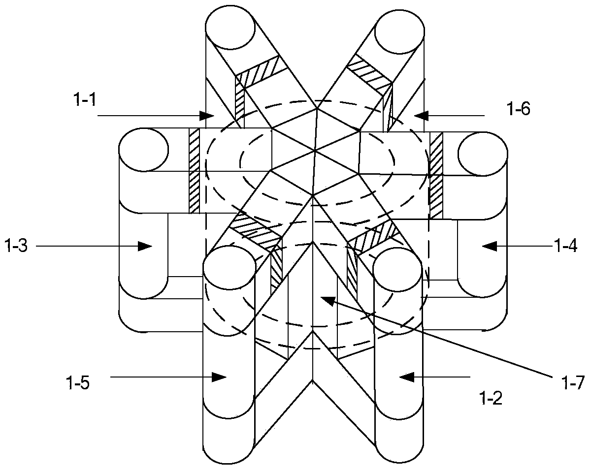
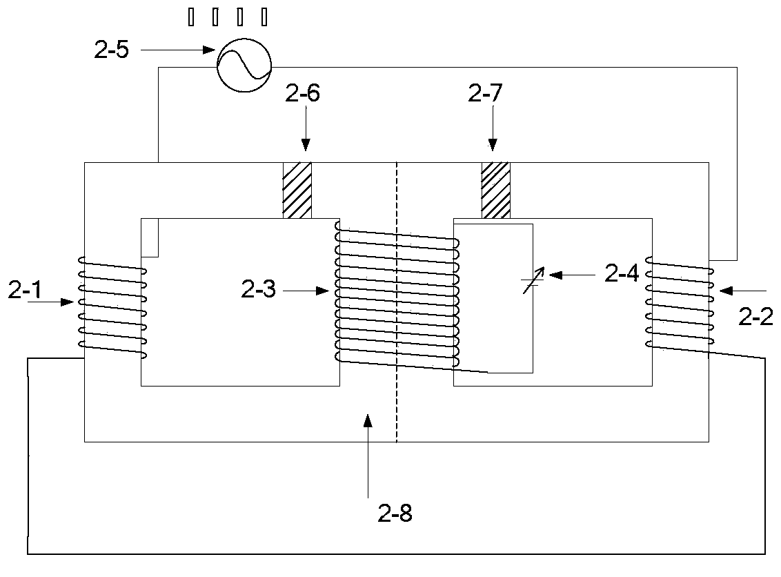
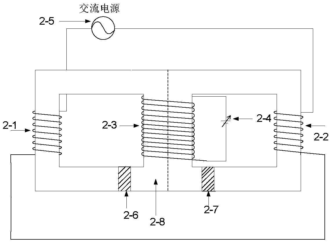
[0027] The iron core reactance regulator of the present invention includes two types: for the single-phase structure, two square-shaped iron cores are set, and each square-shaped iron core has a middle iron core column, a side column, an upper magnetic yoke and a lower magnetic Yoke, the upper yoke opens an air gap of a specific size. In the single-phase structure, the middle columns of the two square-shaped iron cores are combined to form a combined middle column. The DC coil is wound on the combined middle column and connected to the adjustable bias DC source. The adjustable bias DC source can be adjusted according to the needs. Changing the saturation of the iron core changes the output fundamental reactance of the iron core reactance adjusting device. AC coils are wound on the side columns of the two square-shaped iron cores, and the two AC coils are connected at the same end and then connected in series to the power grid.

[0028] For the three-phase structure, set 6 squ...


PUM


Abstract

The invention discloses an iron core reactance regulator with the current control and short-circuit current-limiting functions and a control method thereof. The iron core reactance regulator comprises six square-shaped iron cores, direct current coils and alternating current coils. Each square-shaped iron core comprises a middle column, a side column, an upper magnet yoke and a lower magnet yoke, the six middle columns are combined to form a combined middle column, and the distance between the combined column and each side column adjacent to the combined column is equal. The direct current coils wind the combined middle column and are connected with an adjustable bias direct current source. The alternating current coils wind the side columns, and dotted terminals of the two alternating current coils on the opposite side columns are connected into a whole to be connected to a power grid. Air gaps are formed in the square-shaped iron cores. The control method comprises that when the power grid operates stably, the current value of the adjustable bias direct current source is adjusted to the command value; when the short circuit occurs and the short-circuit current is larger than the stable working current, the output current of the adjustable bias direct current source is lowered to the zero. The iron core reactance regulator is simple in structure, easy to achieve, low in cost and high in reliability.

Description

technical field [0001] The invention relates to a flexible power transmission and transformation device and a power transmission and transformation control method, in particular to an iron core reactance regulator and a control method thereof. Background technique [0002] The power flow control of modern power grids has always been the most concerned issue in the operation of power systems. For large power grids, if the power flow is not effectively controlled, it will have a major impact on the safe operation of the power grid. However, comprehensive power flow control requires a large number of complex and expensive devices, which increases the operating cost of the grid. At the same time, due to the increase in the capacity of the power system, the short-circuit current is also increasing, which not only causes the circuit breaker to fail to disconnect, but also brings a huge instantaneous short-circuit current impact to the power grid. The existing solution includes ins...

Claims


Application Information

Patent Timeline
IPC IPC(8): H02P13/00H01F3/00
Inventor 梅军郑建勇王佳成姚磊钱滢锋刘宾
Owner SOUTHEAST UNIV
Why Eureka
Try Eureka