Supercharge Your Innovation With Domain-Expert AI Agents!

Optical module transmission circuit transmitting HDTV signals

A technology of transmitting circuit and optical module, which is applied in the direction of TV system, electromagnetic transmitter, and cable transmission adapting to optical transmission, and can solve the problems of high optical power, reduced peak optical power of lasers, and increased jitter.

Inactive Publication Date: 2013-12-25
成都网动光电子技术股份有限公司
View PDF6 Cites 3 Cited by
  • Summary
  • Abstract
  • Description
  • Claims
  • Application Information

AI Technical Summary

Problems solved by technology

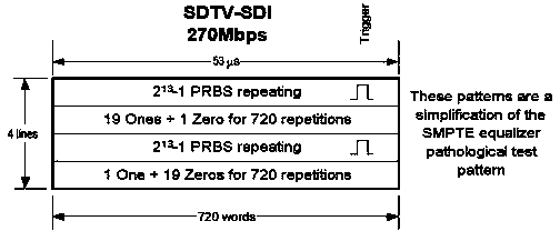
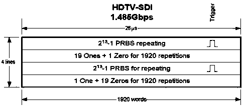
In this way, when 19 "1", a "0", or 19 "0", a "1" are repeatedly transmitted repeatedly, because the time constant of the sample and hold circuit is very small, when transmitting the above-mentioned pathological pattern The signal power will fluctuate greatly, the opening of the eye diagram will become smaller, the jitter will increase, and the jitter of the extinction ratio will also increase sharply, resulting in misjudgment at the receiving end and distortion of the signal image
As shown in Figure 5, in stage "I", 19 "1" and one "0" repeated 720 times or 1920 times in a row, because there are more "1", the effective value of the detection circuit is larger when detecting, and the misjudgment is that the optical power is larger, and the control circuit is gradually reduced Bias current, so that the peak optical power of the laser gradually decreases; in stage "II", 19 "0", one "1", continuous 720 or 1920 repeated transmissions, because there are more "0", the detection circuit is in During detection, the effective value is large, and the optical power is misjudged as small. The control circuit gradually increases the bias current to gradually increase the peak optical power of the laser; after that, if the signal of stage "I" and stage "II" is repeated continuously, The peak power of the laser fluctuates continuously, making it difficult for the receiving end to reply, resulting in bit errors
Unable to meet the pathological pattern transmission of high-definition signals

Method used


Image

  • Optical module transmission circuit transmitting HDTV signals
  • Optical module transmission circuit transmitting HDTV signals
  • Optical module transmission circuit transmitting HDTV signals

Examples


Embodiment Construction

[0022] Combine below Figure 4 And attached Figure 7 Examples The present invention will be further described in detail, and the embodiments of the present invention include but not limited to the following examples.

[0023] exist Figure 4 Among them, the optical power of the laser LD is converted into a photocurrent by the backlight detection diode PD, converted into a voltage signal by the sampling resistor R, held by the capacitor C, and sent to the comparator for comparison, and then drives the triode NPN to adjust the bias current . Because its time constant is small, the optical power has large fluctuations.

[0024] exist Figure 7 Among them, the optical power of the laser LD is converted into a photocurrent by the backlight detection diode PD, converted into a voltage signal by the sampling resistor R, and held by the capacitor C, and then sampled by the peak sampling capacitor after the buffer stage, and then buffered by the buffer stage II Send it to the com...


PUM


Abstract

The invention discloses the design of an optical module transmission circuit transmitting HDTV signals. The optical module transmission circuit meets and supports an SMPTE297-2006 standard and can transmit the signals of SMPTE259M, SMPTE344M, SMPTE292M, SMPTE424MSDI and other pathological code types.

Description

technical field [0001] The invention belongs to the active optoelectronic device class of optical fiber communication products, and it relates to a design scheme for providing a dual-fiber or single-fiber bidirectional high-definition optical module transmitting circuit, especially relates to being compatible with the SMPTE 297-2006 standard, supporting a rate of 50M-3Gbps and SMPTE 259M, SMPTE 344M, SMPTE 292M and SMPTE 424MSDI and other pathological patterns of HDTV signal transmission circuit implementation of photoelectric modules. Background technique [0002] With the continuous improvement of video quality requirements in the field of video transmission and security, users have high requirements for seeing clear images. To meet such requirements, a new type of optical transceiver module is required, which is compatible with the SMPTE 297-2006 standard, supports a rate of 50M to 3Gbps, and can realize pathological code signals such as SMPTE 259M, SMPTE 344M, SMPTE 292M...

Claims


Application Information

Patent Timeline
Patent Type & Authority Applications(China)
IPC IPC(8): H04B10/50H04N7/22
Inventor 汪润泉黄兰
Owner 成都网动光电子技术股份有限公司
Features
  • R&D
  • Intellectual Property
  • Life Sciences
  • Materials
  • Tech Scout
  • Unparalleled Data Quality
  • Higher Quality Content
  • 60% Fewer Hallucinations
Learn More