Method for converting LVDS video signals into MIPI video signals

A video signal and video conversion technology, applied in the direction of standard conversion, instruments, static indicators, etc., can solve problems such as lack of equipment, achieve stable work, high performance, and avoid complex design effects

Active Publication Date: 2013-12-25
WUHAN JINGLI ELECTRONICS TECH
View PDF3 Cites 32 Cited by
  • Summary
  • Abstract
  • Description
  • Claims
  • Application Information

AI Technical Summary

Problems solved by technology

[0004] However, the testing device of MIPI LCD module needs to output the same MIPI test signal, but the existing common LCD module testing device does not have this function, and the common LCD module continues to be produced, and its testing device has not yet entered the replacemen

Method used


Image

  • Method for converting LVDS video signals into MIPI video signals
  • Method for converting LVDS video signals into MIPI video signals
  • Method for converting LVDS video signals into MIPI video signals

Examples


Embodiment Construction

[0042] The present invention will be further described in detail below in conjunction with the accompanying drawings and specific embodiments.

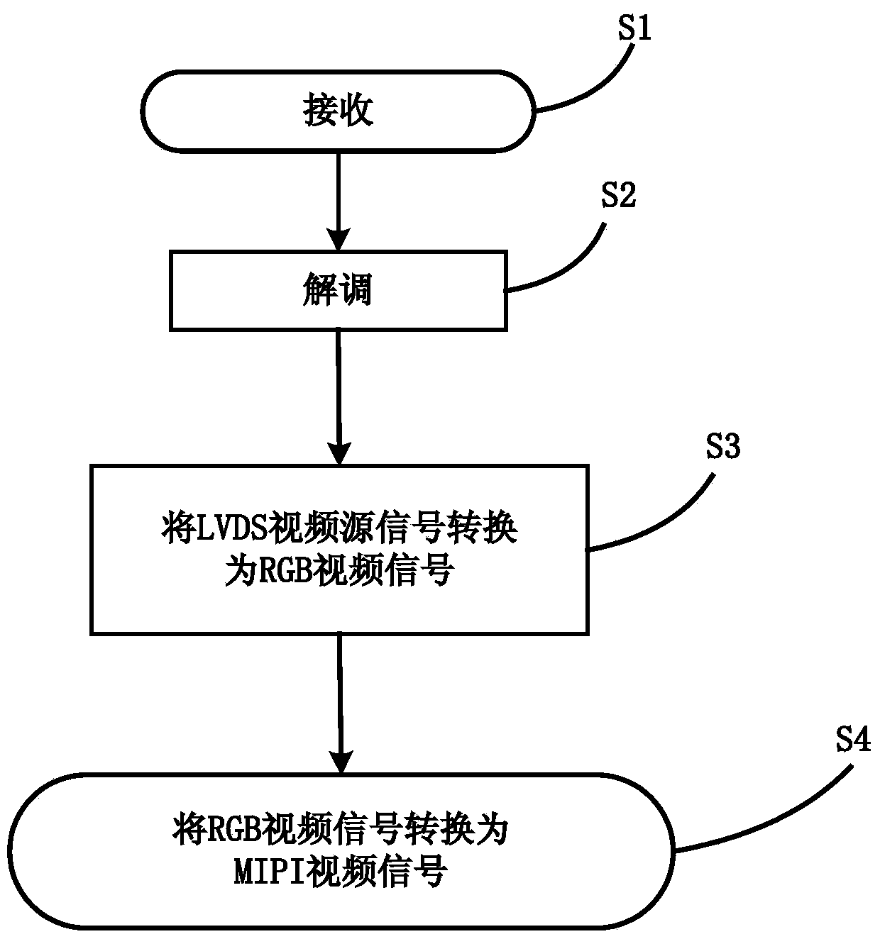
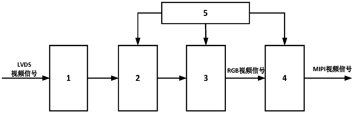
[0043] Such as Figure 1 to Figure 8 Shown, a kind of LVDS video signal of the present invention is converted into MIPI video signal method, comprises the following steps:

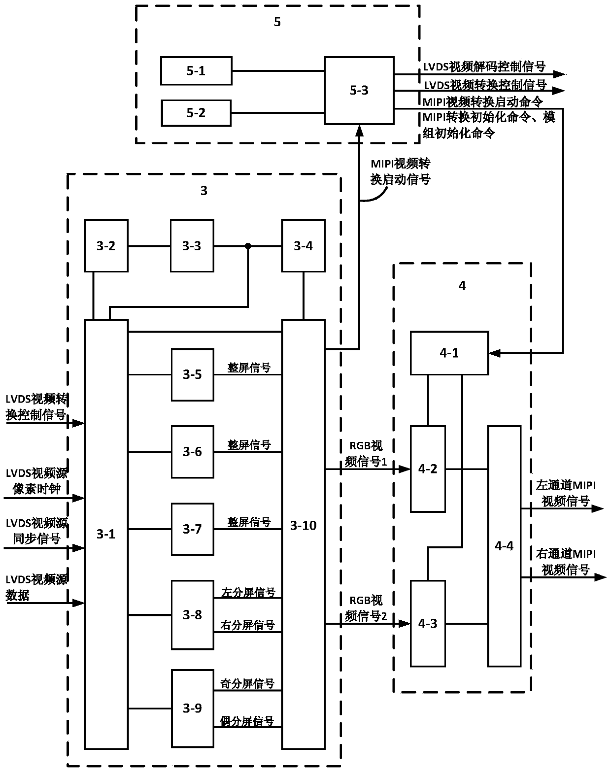
[0044] LVDS video signals include single LINK, double LINK, and quadruple LINK LVDS video signals. The single LINK LVDS video signal, LINK1, transmits all video pixels. The dual LINK LVDS video signal includes LINK1 and LINK2, which transmit odd and even video respectively. pixel; four LINK LVDS video signals, including four links, are sequentially transmitted in LINK1, LINK2, LINK3, LINK4 according to the order of video pixels; MIPI video signals include 4LANE single full screen type, 8LANE left and right split screen type and 8LANE parity split screen type MIPI display module, when the MIPI video signal to be converted is output to the 4LANE single full-screen ...


PUM


Abstract

The invention discloses a method for converting LVDS video signals into MIPI video signals. The method comprises the following steps of 1 respectively and simultaneously receiving and demodulating each link of the LVDS video signals to produce parallel demodulation data and LVDS pixel clocks of all of links; 2 performing video decoding to the parallel demodulation data of all of links to generate LVDS video source signals of all of links, wherein the LVDS video source signals include LVDS video source data and LVDS video source synchronizing signals, and the LVDS pixel clocks are converted into LVDS video source pixel clocks; 3 converting the LVDS video source signals of all of links into RGB video signals; 4 converting the RGB video signals into the MIPI video signals. The method has the advantages of being simple in operation, high in detecting efficiency and low in cost.

Description

technical field [0001] The invention relates to the field of display and testing of liquid crystal modules, in particular to a method for converting LVDS video signals into MIPI video signals. Background technique [0002] Liquid crystal display module (Liquid Crystal Display Module, hereinafter referred to as liquid crystal module) is a key component for liquid crystal display equipment to display normally. It is composed of liquid crystal screen, backlight original, display processing chip and circuit. The structure of the liquid crystal module is precise, the manufacturing process is complicated, and the production process requires high requirements. In order to ensure the yield rate during production, it is necessary to generate various test video signals through a dedicated liquid crystal module testing device and input them to the liquid crystal module for display. Strict and comprehensive testing of its display effect. The display interface and internal display proce...

Claims


Application Information

Patent Timeline
IPC IPC(8): H04N7/01G09G3/00
Inventor 彭骞朱亚凡陈凯沈亚非邓标华
Owner WUHAN JINGLI ELECTRONICS TECH
Why Eureka
Try Eureka