Power measuring apparatus

A technology of power measurement and power, which is applied in the direction of measuring devices, electric power measurement through current/voltage, and measurement of electric variables, etc. It can solve problems such as expensive, unsuitable for power measurement/detection, large and complex structure, etc., and achieve the elimination of AC components Effect

Active Publication Date: 2013-12-25
SIRC CO LTD
View PDF7 Cites 10 Cited by
  • Summary
  • Abstract
  • Description
  • Claims
  • Application Information

AI Technical Summary

Problems solved by technology

In addition, in the PHE-type power measurement device, there is also a limitation in the shape of the magnetic thin film that must be formed with a bridge circuit structure.
These circumstances mean that it is difficult to install PHE-type power measurement devices on special lines such as microstrip lines or co

Method used


Image

  • Power measuring apparatus
  • Power measuring apparatus
  • Power measuring apparatus

Examples


Embodiment Construction

[0150] Hereinafter, embodiments of the present invention will be described with reference to the drawings.

[0151] First, the measurement principle of the power measuring device of the present invention will be described.

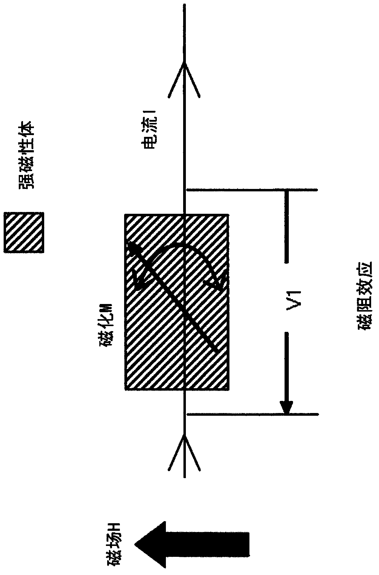
[0152] The power measuring device of the present invention utilizes the magneto-resistance effect in which the resistance value of a ferromagnetic body or a semiconductor changes depending on the angle (orientation) formed by the current and magnetization (spontaneous magnetization). changing phenomenon. use figure 1 To be specific. A current I flows through the ferromagnetic body.

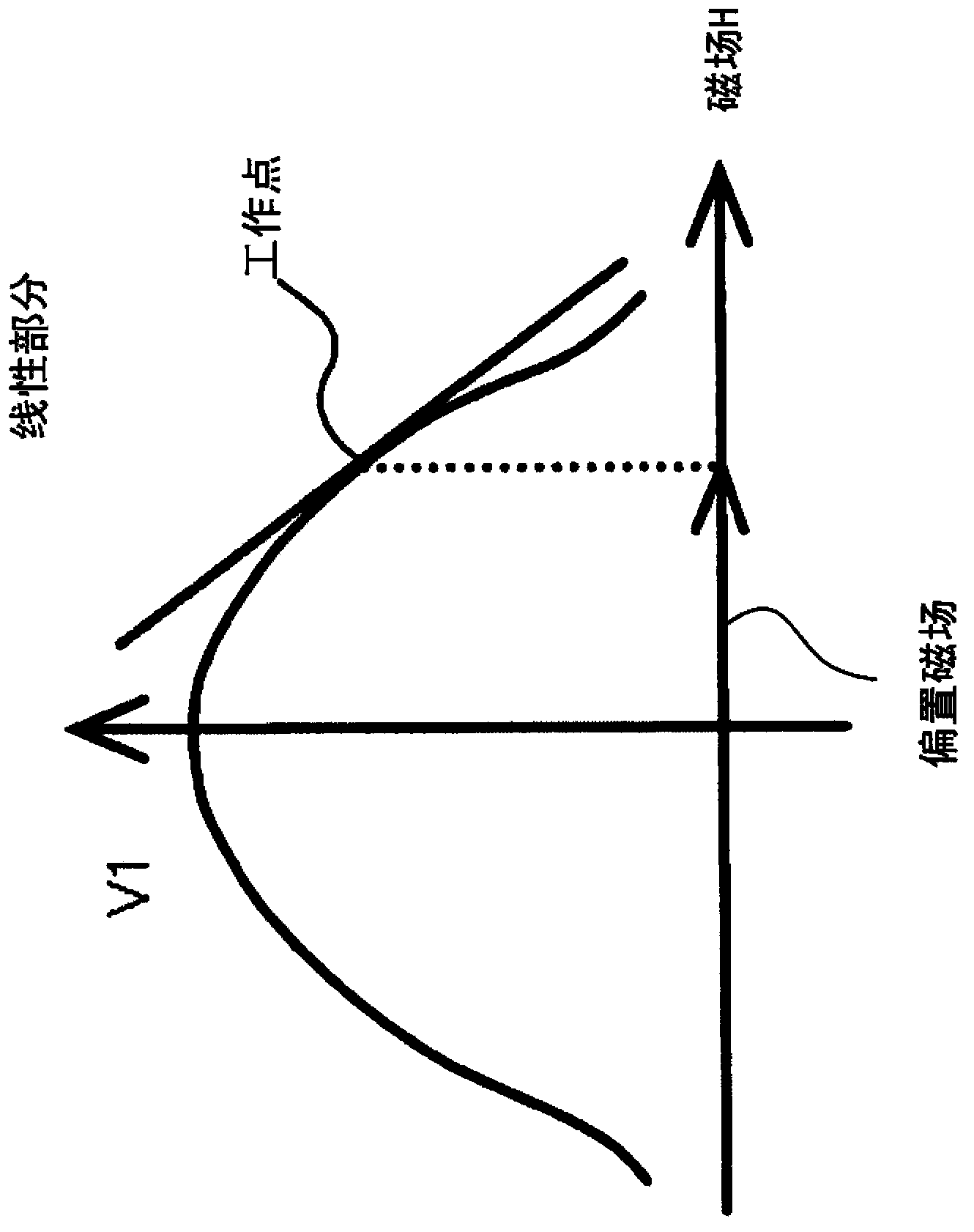
[0153] Here, when the magnetic field H acts on the ferromagnetic material from a direction perpendicular to the direction in which the current I flows, the magnetization M is affected by the magnetic field H and its direction changes. Then, the voltage V1 in the current direction changes. In the magnetoresistance effect in the same direction as the current I of the fe...


PUM


Abstract

The present invention provides power measuring apparatuses of various thin film sensor types, which can easily measure, with a small configuration, power in high frequency circuits and batteries. This power measuring apparatus is provided with: a magnetic film, which is disposed in parallel to a primary conductor having a load current flowing therein; a power feed unit, which is provided with an input/output terminal that supplies an element current to the magnetic film; a bias magnetic field applying unit, which applies a direct current magnetic field that is parallel or perpendicular or diagonal to the magnetization direction of the magnetic film; and a detecting unit, which detects a voltage between the edge portions of the magnetic film in the element current direction. The power measuring apparatus detects merely a direct current voltage composition between the edge portions of the magnetic film in the element current direction.

Description

technical field [0001] The present invention relates to various thin-film sensor-type power measuring devices capable of measuring power of high-frequency circuits, batteries, and the like with a simple and compact structure. Background technique [0002] In recent years, the development of measurement systems including remote power probes has been advancing as the use environment such as the Internet has matured. Conventional power measurement has used an accumulative power meter that converts the used power into the number of rotations of a disc and performs an accumulative calculation. Recently, a sensor for detecting rotation, an ammeter (CT) or a voltmeter (PT) has been added to this integrated power meter, and the power is measured by multiplying by an electronic circuit or a microprocessor. As for the accumulative power meter, its device structure is complex, the device is not only large but also expensive, and because the power is output mechanically, it cannot ...

Claims


Application Information

Patent Timeline
IPC IPC(8): G01R21/08G01R33/09
CPCG01R21/08G01R33/09G01R15/207G01R21/06G01R33/07G01R33/093G01R33/096G01R33/091G01R33/098
Inventor 辻本浩章
Owner SIRC CO LTD
Why Eureka
Try Eureka