
Grinding head installation base of groove grinding machine

A technology for mounting seats and grinding grooves, which is applied to the parts of grinding machine tools, grinding machines, grinding/polishing equipment, etc., and can solve problems such as unusable, low precision, and design errors

Inactive Publication Date: 2014-01-01
PINGHU CITY SHANTE THREAD TOOL
View PDF7 Cites 1 Cited by
  • Summary
  • Abstract
  • Description
  • Claims
  • Application Information

AI Technical Summary

Problems solved by technology

[0004] In order to overcome the defects of the grinding head mounting seat of the ordinary groove grinding machine caused by the wrong design and unreasonable structure of the groove grinding machine, the grinding groove dislocation, low precision, inconsistent standards, and unusable defects, the invention provides a grinding head for the groove grinding machine Mounting seat, the mounting seat of the grinding head of the groove grinding machine is an important part of the groove grinding machine. The advanced thread tool has high precision, the grinding groove is in place, conforms to the standard, and is easy to use

Method used


Image

  • Grinding head installation base of groove grinding machine
  • Grinding head installation base of groove grinding machine

Examples


Embodiment Construction

[0009] The present invention will be further described below in conjunction with accompanying drawing:

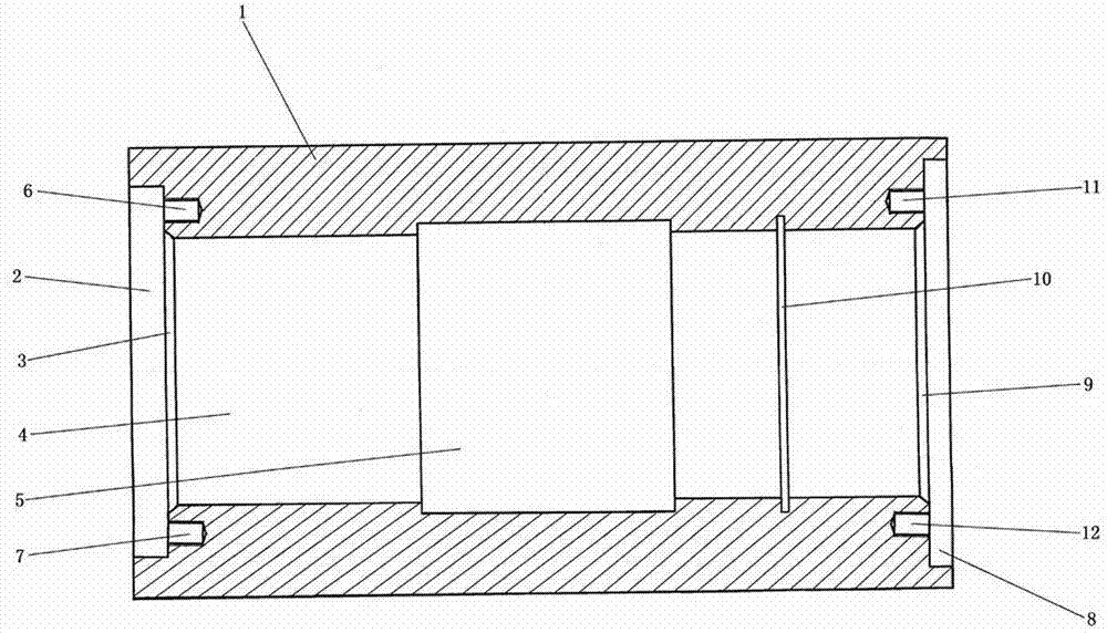
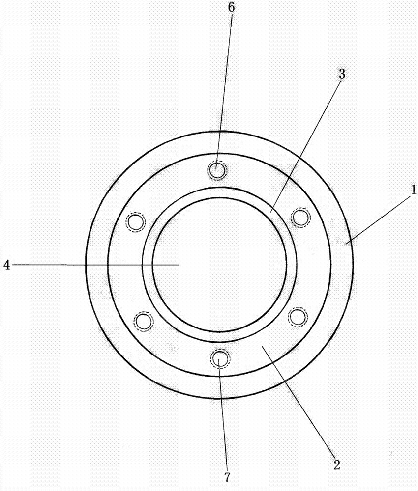
[0010] The grinding head mounting seat of the groove grinding machine includes a metal seat, a round through hole and a threaded hole. It is characterized in that the metal seat 1 is a cylindrical metal seat, placed horizontally, and the diameter of the outer circumference of the metal seat 1 is 215mm, left and right The length is 355㎜; at the center of the left circular surface of the metal base 1, drill a circular through hole 4 to the right. The diameter of the circular through hole 4 is 110㎜. The shape surface has been drilled through the right circular surface of the metal seat 1, and the circular through hole 4 is concentric with the outer circumference of the metal seat 1; on the left circular surface of the metal seat 1, a left circular hole 2 is drilled, and the left circular The diameter of hole 2 is 155㎜, and the length of left and right is 15㎜; the left round ho...


PUM

PropertyMeasurementUnit
Diameteraaaaaaaaaa
Lengthaaaaaaaaaa

Abstract

The invention discloses a grinding head installation base of a groove grinding machine. The installation base is a cylindrical metal base and is arranged transversely. A circular through hole is drilled rightwards in the center of a left circular face of the metal base, the circular through hole and the outer circumference of the metal base are concentric circles, a left circular hole is also drilled in the left circular face of the metal base, the left circular hole and the circular through hole are concentric circles and are communicated, a left taper hole is then formed rightwards in the right face of the left circular hole, the left taper hole and the circular through hole are communicated, the center line of the left taper hole coincides with the center line of the circular through hole, a middle circular hole is formed in the middle of the circular through hole, the middle circular hole and the circular through hole are concentric circles and are communicated, the center of the middle circular hole is also the center of the metal base, six left threaded holes are evenly drilled in the right face of the left circular hole, a right circular hole is drilled in the right circular face of the metal base, the right circular hole and the circular through hole are concentric circles and are communicated, a right taper hole is formed leftwards in the left face of the right circular hole, the right taper hole and the circular through hole are communicated, the center line of the right taper hole coincided with the center line of the circular through hole, a narrow circular hole is formed between the right taper hole and the middle circular hole, the narrow circular hole and the circular through hole are concentric circles and are communicated, and six threaded holes are evenly drilled in the left face of the right circular hole.

Description

[0001] technical field [0002] The invention relates to a grinding head mounting seat of a groove grinding machine, specifically a grinding head mounting seat of a new type of groove grinding machine for grinding grooves on threaded tools used on various machine tools, such as taps, and is used for machine tools. A new equipment for thread tool processing - an important part of the new groove grinding machine. Background technique [0003] Usually, what must be used in machinery manufacturing and processing plants: one is the machine tool, and the other is the tools used on the machine tool. Both are indispensable. Good machine tools such as CNC machine tools use thread tools such as taps, etc., and the quality of thread tools To upgrade the grade, it is necessary to process the threaded tools so that the threaded tools meet the standards, the quality is good, and the products are superior; and to achieve this goal, it is necessary to complete the groove grinding machine...

Claims


Application Information

Patent Timeline
IPC IPC(8): B24B19/02B24B41/04
CPCB24B19/02B24B41/04
Inventor 沈雪英王金根袁家栋张美宝
Owner PINGHU CITY SHANTE THREAD TOOL
Learn More