Tool and operation method thereof

A technology of tools and tool components, applied in the direction of motor tools, manufacturing tools, wrenches, etc., can solve problems such as user neglect of update configuration, user error input, tools not operating as expected, etc., to achieve energy supply and simplify applications and transport effects

Active Publication Date: 2014-01-01
ROBERT BOSCH GMBH
View PDF7 Cites 4 Cited by
  • Summary
  • Abstract
  • Description
  • Claims
  • Application Information

AI Technical Summary

Problems solved by technology

[0007] The current disadvantage of this solution is that, when manually updating the configuration of the control device, the user may enter incorrectly or the updated configuration may be completely ignored by the user.
The consequence may then be that the tool does not perform as expected or wears out even more quickly because the components are not functioning in their normal operating conditions

Method used


Image

  • Tool and operation method thereof
  • Tool and operation method thereof
  • Tool and operation method thereof

Examples


Embodiment Construction

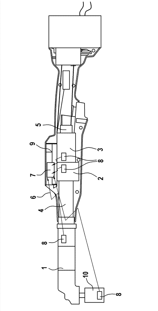
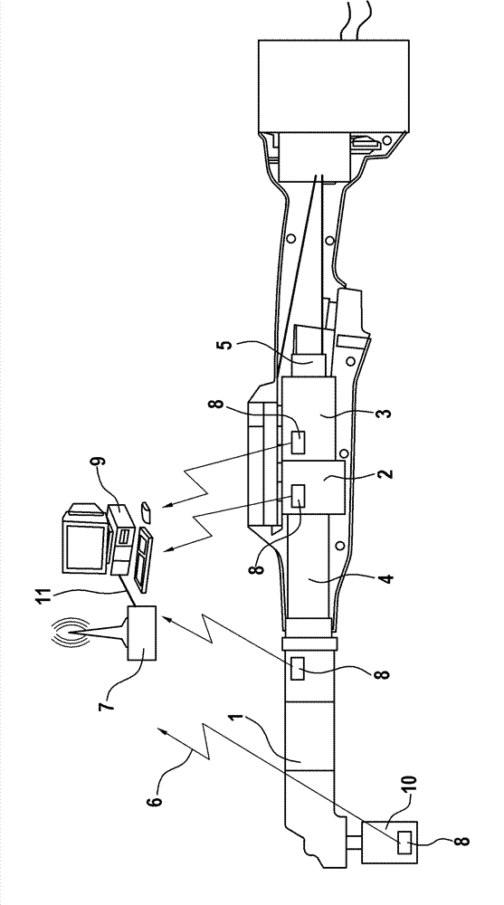
[0030] figure 1 An example of a battery-operated screw spindle is shown, and the screw spindle also includes a device for running on the power grid. The screw spindle includes a first tool assembly in the form of a drive mechanism 3 and a second tool assembly in the form of a driven mechanism 1, and preferably includes other tools such as, for example, the transmission mechanism 2, the torque sensor 4, and the rotor position detector 5. The components, which are mutually arranged inside the housing and connected to each other, enable the driven mechanism 1 to be driven by means of the drive mechanism 3.

[0031] The tool assembly 1-5 includes a self-contained and wirelessly working data communication unit 8 with a memory and an energy supply unit. The energy supply unit is implemented in such a way that the energy supply unit can be inductively coupled to an external energy source to provide the energy required for operating the data communication unit 8.

[0032] In addition, the...


PUM


Abstract

A tool and an operation method thereof are provided. The invention relates to the tool with tool assemblies (1 to 5). The tool assemblies include a self-locking wireless data communication unit (8) with a memory and an energy supply unit. The tool arrangement is improved through a tool controller.

Description

Technical field [0001] The invention relates to industrial and electrically driven tools, in particular screwing systems or riveting systems. Background technique [0002] For example, screwing systems are known from the background art. [0003] Such a screwing system can be realized, for example, by means of the following devices: a superior screwing control device (basic station, screwing controller) for one or more screwing tools, according to the control of the spindle of the screwing system Power consumption required power components, one or more screw spindles. The screw spindle usually includes at least one driven mechanism, a transmission mechanism and a motor. The driven mechanism can be driven by means of a motor and using a transmission mechanism. In addition to the screwing control device, an SPS for coordinating multiple screwing systems can also be provided. Optionally, there may also be one or more industrial computers and peripheral devices such as printers for ...

Claims


Application Information

Patent Timeline
Patent Type & Authority Applications(China)
IPC IPC(8): B25B21/00
CPCB25B21/00B25B23/147B25F5/00
Inventor A.弗卢雷尔M.里格尔
Owner ROBERT BOSCH GMBH
Why Eureka
Try Eureka