Metal insert positioning and loading device in injection moulding process

An injection molding process and metal insert technology, applied in coating and other directions, can solve the problems of high labor intensity, high labor intensity and slow feeding speed of workers, so as to reduce the risk of defective parts, reduce labor intensity, and improve production. The effect of efficiency

Inactive Publication Date: 2014-01-01
GUANGDONG TECHN COLLEGE OF WATER RESOURCES & ELECTRIC ENG
View PDF2 Cites 16 Cited by
  • Summary
  • Abstract
  • Description
  • Claims
  • Application Information

AI Technical Summary

Problems solved by technology

However, the following problems often exist in the actual processing process: 1. The working environment of the workers is harsh. The molding temperature of the injection molding machine is generally above 200 °. ° above, it is difficult for ordinary people to work in this temperature environment for a long time; 2. The labor intensity of workers is high
The injection molding time is generally 30 seconds to 1 minute, 8 hours a day, workers have to repeat the operation about 4,000 times, and the labor intensity is very high; 3. In the insert injection molding process, the number of individual small-sized workpieces is relatively large, for example To make a 20mm diameter wheel of a toy car with bearings, generally 16 pieces are molded each time, and the positioning accuracy is relatively high. If manual positioning is used, not only the feeding speed is slow, but also the positioning accuracy is difficult to ensure

Method used


Image

  • Metal insert positioning and loading device in injection moulding process
  • Metal insert positioning and loading device in injection moulding process
  • Metal insert positioning and loading device in injection moulding process

Examples


Embodiment Construction

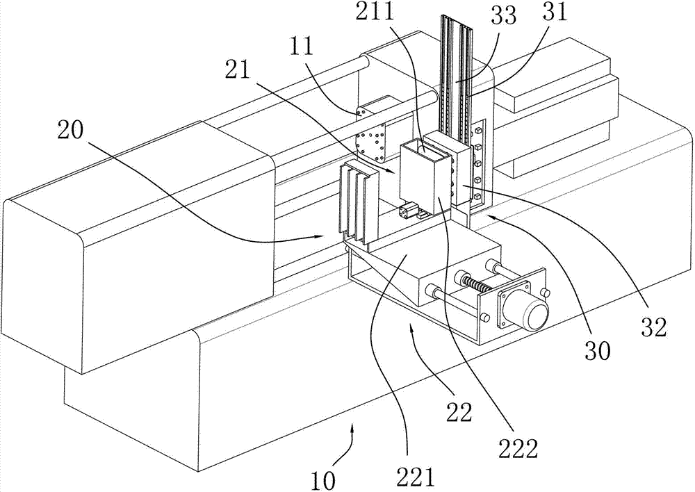
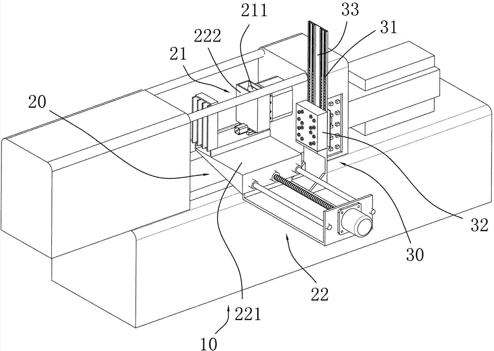
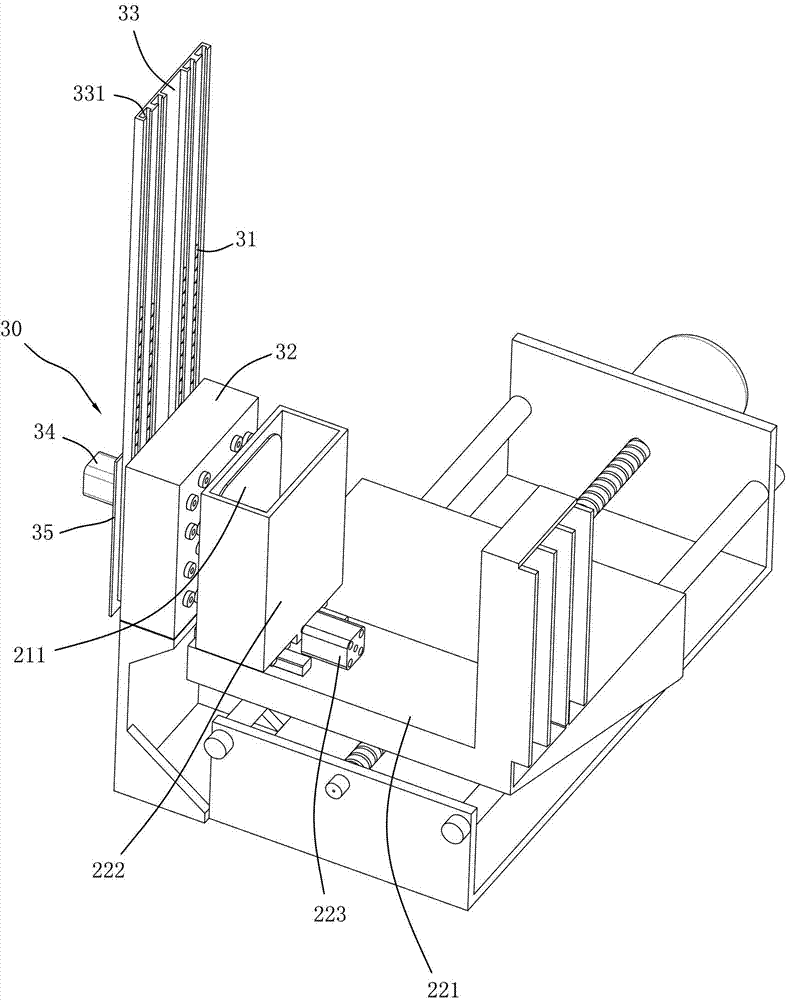
[0028] refer to Figure 1 to Figure 11 , a metal insert positioning and feeding device in the injection molding process, which is used to fill and position the metal insert into the cavity of the injection mold, including an insert feeding part 30 on which a metal insert 31 is stored on the body 10 And the insert positioning mechanism 20, the insert positioning mechanism 20 includes a magnetic adsorption device 21 that can absorb the metal insert 31 in the insert supply part 30 and drives the magnetic adsorption device after the magnetic adsorption device 21 absorbs the metal insert 31 21 moves to the injection mold to load the metal insert 31 into the driving device 22 positioned in the mold cavity 11 .

[0029] In this embodiment, the metal insert 31 is an annular metal insert, and a plurality of metal inserts 31 arranged in a fixed shape are loaded and positioned into the mold cavity 11 through the positioning and feeding device.

[0030] The insert feeding part 30 and the...


PUM

PropertyMeasurementUnit
diameteraaaaaaaaaa

Abstract

The invention discloses a metal insert positioning and loading device in an injection moulding process. The metal insert positioning and loading device is used for filling and positioning a metal insert into a mould cavity of an injection mould, and comprises an insert feeding part and an insert positioning mechanism, wherein the insert positioning mechanism comprises a magnetic adsorption device and a driving device; the magnetic adsorption device is used for adsorbing the metal insert in the insert feeding part; the driving device is used for driving the magnetic adsorption device to move to the injection mould to fill and position the metal insert into the mould cavity after the magnetic adsorption device adsorbs the metal insert. The magnetic adsorption device of the insert positioning mechanism automatically fills and positions the metal insert into the mould cavity through the driving device after adsorbing the metal insert in a magnetic adsorption manner, the traditional manual metal insert filling mode is abandoned, and manual work is replaced by a machine, so the production efficiency is greatly improved, the labor intensity of workers is reduced, the risk of defective parts caused by misoperation of the workers is reduced, and high-efficiency, high-speed and high-quality production is guaranteed. The metal insert positioning and loading device is applied to the technical field of injection moulds.

Description

technical field [0001] The invention relates to the technical field of injection molds, in particular to a positioning device for an insert in an injection mold. Background technique [0002] Insert injection molding refers to a molding method in which pre-prepared inserts of different materials are placed in the mold and molten plastic is injected, and the molten plastic and inserts are bonded and solidified to form an integrated product. This processing method is widely used in the injection molding industry. Metal inserts such as bearings, screws, and nuts can be added to plastics to make toy car wheels, handles, doors and other accessories. [0003] In the current insert injection molding process, the inserts are usually positioned and loaded manually, that is, the inserts are first positioned in the mold, and then injection molded by the injection molding machine. However, the following problems often exist in the actual processing process: 1. The working environment ...

Claims


Application Information

Patent Timeline
Patent Type & Authority Applications(China)
IPC IPC(8): B29C45/14B29C45/17
CPCB29C45/14008
Inventor 梁健曾杰华曾杰豪
Owner GUANGDONG TECHN COLLEGE OF WATER RESOURCES & ELECTRIC ENG
Why Eureka
Try Eureka