Under-pressure drill tripping method used under top drive drilling machine

A technology of top drive and drilling rig, applied in the direction of drill pipe, drill pipe, earthwork drilling, etc., to achieve the effect of simple design, reducing labor intensity and ensuring personal safety

Active Publication Date: 2014-01-01
BC P INC CHINA NAT PETROLEUM CORP +1
View PDF2 Cites 4 Cited by
  • Summary
  • Abstract
  • Description
  • Claims
  • Application Information

AI Technical Summary

Problems solved by technology

[0006] In order to solve the above-mentioned technical problems, the present invention proposes a method for tripping under pressure under top drive drilling rigs in oil and gas (geological prospecting) drilling and completion, which solves the problem that conventional tripping under pressure under top drive drilling rigs cannot Difficulties in installation and operation on the drill floor

Method used


Image

  • Under-pressure drill tripping method used under top drive drilling machine

Examples


Embodiment 1

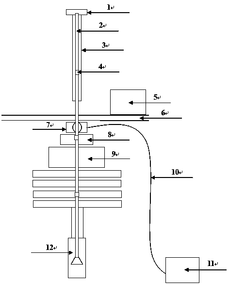
[0035] Refer to the attached figure 1 , the best implementation mode of the present invention is, comprises the following steps:

[0036] Install hydraulic slips under the drill floor, and measure the pressure of the wellhead that needs to be tripped under pressure; when the tested wellhead pressure is less than or equal to 5Mpa, use the top drive 11 to connect the drilling tool 2, and use the top drive 11 to implement under pressure When tripping out, the number of drilling tools 2 that are lifted or lowered is 1-3; when the number of drill tools 2 that is lifted or lowered reaches 1-3, the hydraulic slips arranged under the drill floor are activated, Make the hydraulic slips clamp the drilling tool 2, and the clamping force of the hydraulic slips is ≥ 3T; when starting the top drive 11 and lifting the drilling tool 2, the drilling tool 2 stuck at the wellhead is separated, and the unloaded The drilling tool 2 is placed on the rack; when the drilling tool 2 is lowered, the d...

Embodiment 2

[0037] Embodiment 2, the mode of pulling out drilling tool 2 in the well:

[0038] First test the wellhead with a pressure of 5MPa, use the top drive 11 to prevent the drilling tool 2 from going up, pull out two 9m-long drill collars at the wellhead, slowly lift them to the drill floor 6, and their joints are located 20cm~100cm above the drill floor 6, and open The hydraulic (pneumatic) pressure switch activates the hydraulic (pneumatic) slips and clamps the drill collar. At this time, the camera installed near the hydraulic (pneumatic) slips is used to monitor the opening and closing of the slips and confirm the clamping. After tightening, use iron driller or hydraulic tongs to disassemble the pipe string on the drill floor 6, remove the disassembled drill collar, and then lower the top drive 11 to the vicinity of the drill floor 6, and then Connect the remaining drill collars in the well, loosen the hydraulic (pneumatic) dynamic slips, and then use the top drive 11 to lift t...

Embodiment 3

[0039] Embodiment 3, the drilling tool 2 is lowered into the well:

[0040] Test the wellhead with a pressure of 3MPa. Use the camera installed near the hydraulic (pneumatic) slips to monitor the opening and closing of the slips. After confirming the release, use the top drive 11 to slowly lower a column (3 drill collars) , until the drill collar joint is 620cm~100cm above the drill floor, stop lowering, turn on the hydraulic (air) pressure switch, start the hydraulic (air) slips, and clamp the drill collar. After confirming the clamping, release the top drive 11, Top drive 11 connects a new column and moves it to the wellhead, uses iron drillers or hydraulic tongs to connect with the drill collar in the well, then releases the hydraulic (gas) slips, and uses top drive 11 to lower the new column. Slowly run into the well and repeat the operation until 5 to 10 columns of drilling tools 2 are scheduled to be lowered into the well.


PUM


Abstract

The invention discloses an under-pressure drill tripping method used under a top drive drilling machine and belongs to the technical field of an under-pressure drill tripping tool. The method comprises the following steps that a hydraulic slip is arranged under a drill stand, and in addition, a well mouth requiring the under-pressure drill tripping implementation is subjected to pressure measurement; when the pressure of the tested well mouth is smaller than or equal to 5Mpa, a top drive connecting drill tool is adopted, and when a top drive is adopted for implementing the under-pressure drill tripping, the number of the upwards lifted or downwards placed drill tool(s) is 1 to 3; when the number of the upwards lifted or downwards placed drill tool(s) is 1 to 3, the hydraulic slip arranged under the drill stand is started, the drill tools are clamped by the hydraulic slip, and the clamping force of the hydraulic slip is greater than or equal to 3T; the top drive is started, when the drill tools are upwards lifted, the drill tools clamped in the well mouth are separated, and in addition, the dismounted drill tools are placed on a pipe rack; and when the drill tools are downwards placed, the connected drill tools are conveyed into a well by the downward pressure of the top drive. The method solves the difficult problem that a conventional under-pressure drill tripping device under the top drive drilling machine cannot be mounted or operated on the drill stand.

Description

[0001] technical field [0002] The invention relates to a tripping method under pressure used in oil and gas (geological prospecting) drilling and completion, and belongs to the technical field of tripping under pressure. Background technique [0003] During underbalanced drilling, once the reservoir is opened, the oil and gas in the downhole must go up along the wellbore. If the drilling operation is performed, the drilling fluid density is mainly increased to form a positive pressure difference at the bottom of the well to prevent the formation of fluid in the reservoir. Entering the wellbore for safe tripping operations, however, this method will cause a large amount of drilling fluid to invade the reservoir, causing serious reservoir damage. [0004] In order to avoid reservoir damage, it is very necessary to use pressure tripping technology in the process of underbalanced drilling. At present, the technology of tripping under pressure mainly adopts snubbing device, su...

Claims


Application Information

Patent Timeline
Patent Type & Authority Applications(China)
IPC IPC(8): E21B19/00
Inventor 魏强肖润德韩烈祥肖新宇杨玻潘登
Owner BC P INC CHINA NAT PETROLEUM CORP
Why Eureka
Try Eureka