Oil scavenge arrangement

A gear box and ring gear technology, applied in the direction of hoisting device, transmission device, transmission device parts, etc., can solve the problem of no centrifugal force, and achieve the effect of reducing overheating

Inactive Publication Date: 2014-01-01
ROLLS ROYCE PLC
View PDF0 Cites 13 Cited by
  • Summary
  • Abstract
  • Description
  • Claims
  • Application Information

AI Technical Summary

Problems solved by technology

The downside is that epicyclic gearboxes with planetary arrangements do not have the centrifugal force to expel the oil because the ring gear does not rotate

Method used


Image

  • Oil scavenge arrangement
  • Oil scavenge arrangement
  • Oil scavenge arrangement

Examples


Embodiment Construction

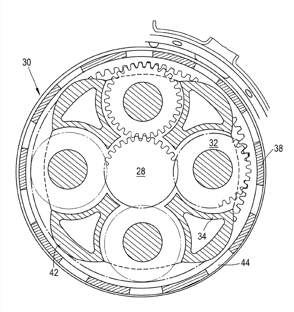
[0026] refer to figure 1 , the two-shaft gas turbine engine 10 has a main axis of rotation 9 . The engine 10 includes an air intake 12 and a propulsion fan 23 which generates two air streams A and B. Gas turbine engine 10 includes a core engine 11 having a low pressure booster compressor 14 in axial flow A, a high pressure compressor 15 , combustion equipment 16 , a high pressure turbine 17 , a low pressure turbine 19 and a core exhaust nozzle 20 . A nacelle 21 surrounds the gas turbine engine 10 and defines a bypass duct 22 in axial flow B and a bypass exhaust nozzle 18 . The fan 23 is attached to and driven by the low pressure turbine 19 via a shaft 26 and an epicyclic gearbox 30 .

[0027] Gas turbine engine 10 operates in a conventional manner such that air in core airflow A is accelerated and compressed by high pressure booster compressor 14 and introduced to high pressure compressor 15 where further compression occurs. The compressed air discharged from the high press...


PUM


Abstract

An epicyclic gearbox oil scavenge arrangement. The epicyclic gearbox is of the planetary or differential type and comprises an input sun gear (28); a plurality of planet gears (32) that mesh with the sun gear (28) and are driven therefrom; an annular planet carrier (34) that couples the planet gears (32) in known relative orientation and is configured to precess around the sun gear (28); and a ring gear (38) that meshes with each planet gear (32). The ring gear (38) comprises ejection apertures (44) that extend radially therethrough and the planet carrier (34) comprises at least one lobe (42) that extends radially from the periphery of the planet carrier.

Description

technical field [0001] The present invention relates to an oil pick-up arrangement for epicyclic gearboxes. It is used in particular in planetary arrangements of epicyclic gearboxes, where the sun gear is coupled to the input shaft and the planet carrier advances around the sun gear and is coupled to the output shaft. Background technique [0002] It is known to lubricate and cool epicyclic gearboxes by introducing oil. In use, the oil becomes used, which raises its temperature and can also attract debris. This oil must therefore be periodically drained and replaced with fresh oil in order to prevent or reduce the risk of overheating and hydraulic locking. [0003] It is known to drain oil from epicyclic gearboxes in a star arrangement, where the planet carrier is fixed and the ring gear is coupled to the output shaft and progresses around the input sun gear. Typically, the rotation of the ring gear creates enough centrifugal force to expel the oil from the gearbox. [0...

Claims


Application Information

Patent Timeline
IPC IPC(8): F16H57/04F16H57/023F16H1/32F16H55/02
CPCF16H57/082F05D2260/40311F02C3/107F16H1/28F16H57/0486F01D25/18F02C7/36F16H57/0427F16H57/0409F01D25/28
Inventor M.理查兹
Owner ROLLS ROYCE PLC
Why Eureka
Try Eureka