Radiant floor heating fan coil refrigerated wind source heat pump device
A technology for radiant heating and heat pump devices, which is applied in heating and ventilation control systems, heating and ventilation safety systems, refrigerators, etc., can solve the problems of system imbalance, complicated pipelines, and high cost, and achieves low input power and high equipment input power. The effect of promotion value and easy installation
- Summary
- Abstract
- Description
- Claims
- Application Information
AI Technical Summary
Problems solved by technology
Method used
Image


Examples
Embodiment 1
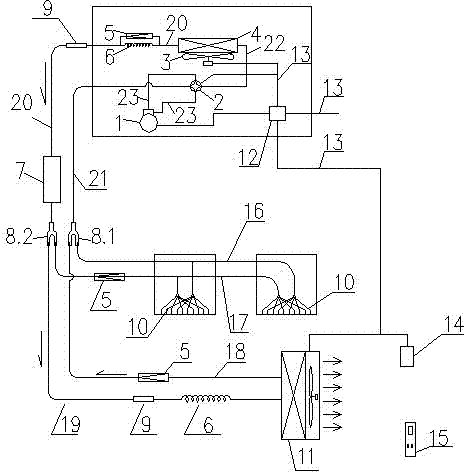
[0015] Embodiment 1: as figure 1 As shown in the figure, an air source heat pump device for radiant floor heating and air tray refrigeration includes a compressor. The compressor 1 is equipped with a pipeline 23 connected thereto. The other end of another connected pipeline 21 is connected to the three-way 8.1, and there is also a pipeline 22 connected to the four-way valve, one end of which is connected to the four-way valve 2, the other end is connected to the heat exchanger 4, and the fan 3 is installed on the heat exchanger 4, and another tee 8.2 is also installed in the device, and the tee 8.2 is connected with one end of the connecting pipe 20, and the other end of the connecting pipe 20 is connected with the heat exchanger 4. The connecting pipe 20 of the device 4 and the tee 8.2 is also equipped with a one-way valve 5, a capillary 6, a filter 9 and a liquid storage tank 7 in sequence, wherein the one-way valve 5 and the capillary 6 are connected in parallel and ins...
Embodiment 2
[0016] Embodiment 2: An air source heat pump device for floor radiant heating and air tray cooling. This embodiment is a device that directly provides cooling and heating from the floor. Its specific structure is as figure 1 shown.
[0017] exist figure 2 Middle: The compressor 1 is connected to the four-way valve 2 through the pipeline 23, the four-way valve 2 is connected to the three-way 8.1 through the pipeline 21, and the heat exchanger 4 is connected through the pipeline 22, and the fan 3 is installed on the heat exchanger 4 And through the power and control line 13, it is connected with the host power supply and the control panel 12, and between the heat exchanger 4 and the tee 8.2, through the connecting pipe 20, the heat exchanger 4 is sequentially connected with a check valve 5, a capillary 6, and a filter. 9. The liquid storage tank 7, wherein the one-way valve 5 and the capillary 6 are connected in parallel and installed on the connecting pipe 20. Between the i...
Embodiment 3
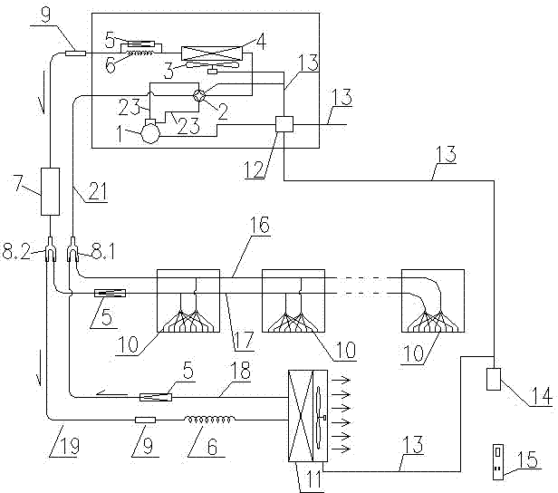
[0018] Embodiment 3: An air-source heat pump device for floor radiant heating and air-disc cooling, in which the floor tube bundles are increased to three groups.
[0019] Others are identical with embodiment 2.
[0020] Such as image 3 As shown, compressor, four-way valve, fan, heat exchanger, one-way valve, capillary tube, liquid storage tank, tee, filter, coil tube bundle, indoor fan coil, power junction box and main control board, power supply Wires and control harnesses, indoor temperature sensor probes and control boxes, remote controllers, pipelines, etc. are all installed according to the design drawings, the same as in Embodiment 2; the difference is that the coil tube bundles 10 are changed from two groups to three groups.
PUM
 Abstract
Description
Claims
Application Information
 - R&D
- Intellectual Property
- Life Sciences
- Materials
- Tech Scout
- Unparalleled Data Quality
- Higher Quality Content
- 60% Fewer Hallucinations
Browse by: Latest US Patents, China's latest patents, Technical Efficacy Thesaurus, Application Domain, Technology Topic, Popular Technical Reports.
© 2025 PatSnap. All rights reserved.Legal|Privacy policy|Modern Slavery Act Transparency Statement|Sitemap|About US| Contact US: help@patsnap.com