
Method for arranging network traffic flow detectors based on road network topological relation

A technology of traffic flow and topological relationship, applied in the traffic control system of road vehicles, traffic control systems, instruments, etc., can solve the problems of difficulty in popularizing existing methods, slow update speed of OD matrix, high investigation cost, etc.

Active Publication Date: 2014-01-01
TONGJI UNIV
View PDF6 Cites 23 Cited by
  • Summary
  • Abstract
  • Description
  • Claims
  • Application Information

AI Technical Summary

Problems solved by technology

The acquisition of historical OD matrix requires regular large-scale traffic demand surveys. The high cost of surveys makes many cities discouraged. Even in some cities with good economic conditions, such surveys are only carried out every few years. The update speed of OD matrix very slow
At the same time, many research results also show that the traveler's route choice behavior is very complicated, and the existing assumptions are not very consistent with reality.
[0004] A series of problems such as unclear methods, high cost of prior information acquisition, and traveler's route choice behavior assumptions deviate from reality have made it difficult to popularize existing methods in practical applications.

Method used


Image

  • Method for arranging network traffic flow detectors based on road network topological relation
  • Method for arranging network traffic flow detectors based on road network topological relation
  • Method for arranging network traffic flow detectors based on road network topological relation

Examples


Embodiment 1

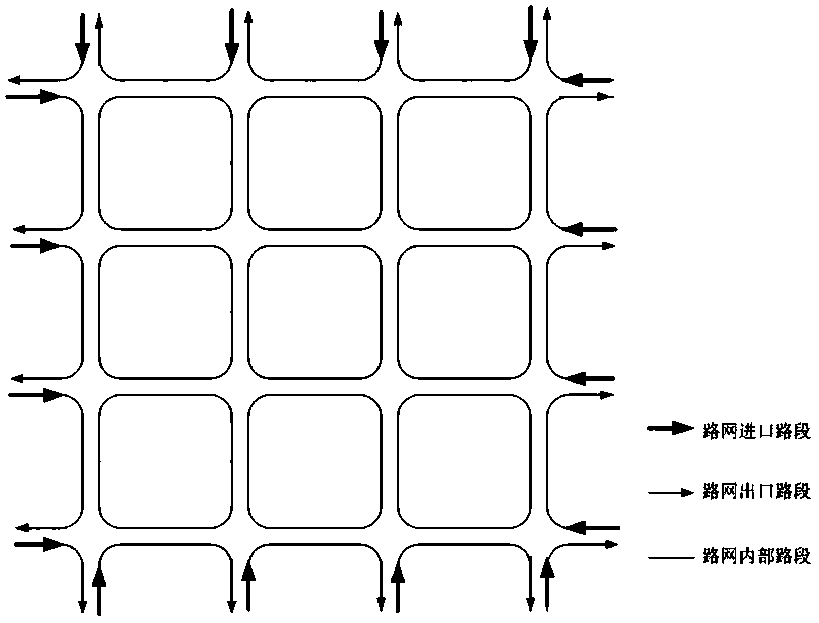
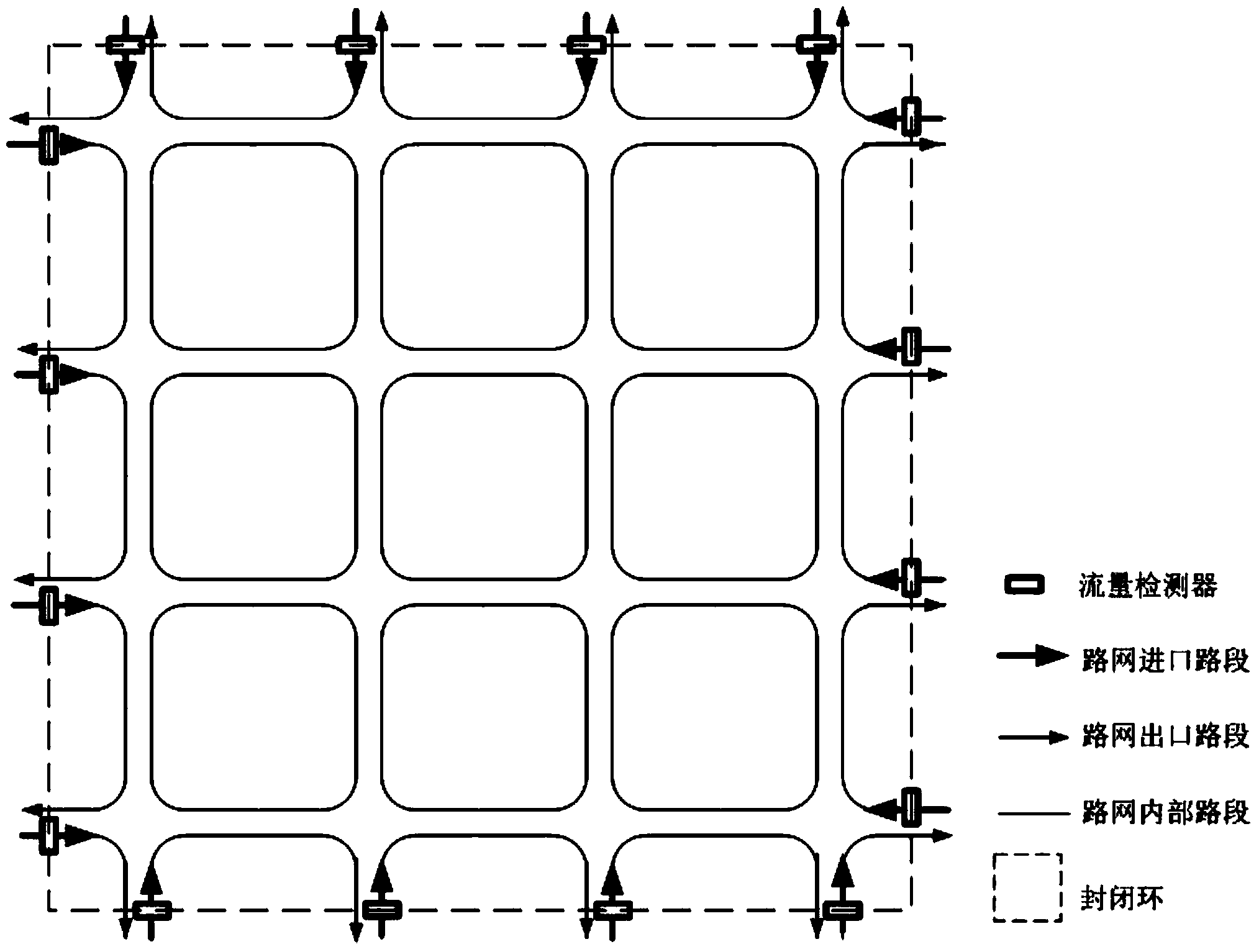
[0053] Embodiment 1: adopt the method of the present invention to give Figure 4 The flow detector layout optimization scheme of the road network shown. For the convenience of description, this embodiment adopts a small road network composed of 9 one-way road sections, wherein road section 7 is a road section with traffic generation.

[0054] According to the method steps and attached figure 1 shown in the flow, Figure 4 The steps of road network detector layout optimization are as follows:

[0055] 1) Road section classification: Road section 9 is only the entrance section of intersection 1, road section 1 is only the exit section of intersection 3, and road section 2 is only the exit section of intersection 4, so the final result of road section classification is: road network entrance section Set {9}; road network exit section set {1,2}; road network internal road section set {3,4,5,6,7,8}.

[0056] 2) The processing of road sections with traffic generation in the road...


PUM


Abstract

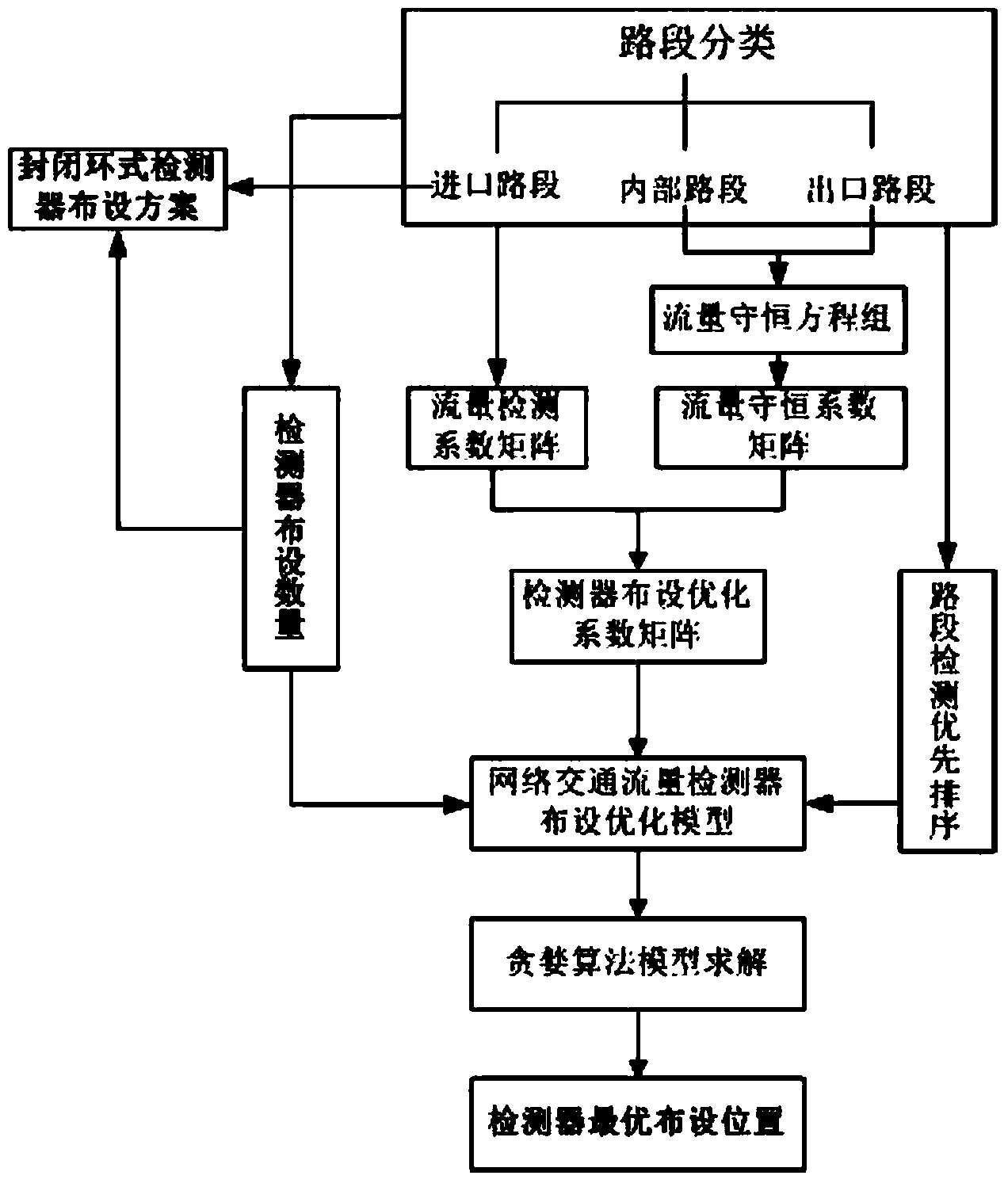
The invention provides a method for arranging network traffic flow detectors based on a road network topological relation. Firstly, road sections in a road network are divided into road network inlet road sections, road network outlet road sections and road network internal road sections, traffic generation road sections are determined, and the number of needed least detection road sections is the sum of the number of the road network inlet road sections and the number of traffic generation road sections; then according to the intersection traffic flow conservation law, a road network flow conservation equation set is built; then detection priority ordering is carried out according to road levels and costs, and the reversed order of the priority order is used as a detection weight; finally the highest priority of a detection road section set is used as an optimization target, a detector arranging optimization model is built with the number of arranged detectors and the order of a detector optimization coefficient matrix as restraint conditions, and the greedy algorithm is used for solving to determine the optimal arranging positions of the detectors. Construction and maintenance cost of a road network traffic flow detection system can be lowered, and OD matrix investigation high cost and distortion assumption of a traveler path choice motion are avoided.

Description

technical field [0001] The invention belongs to the technical field of urban road traffic and relates to network traffic flow detection. Background technique [0002] The acquisition of network traffic flow is very important in the fields of urban traffic planning, design and control management. Due to the large scale of urban road networks (usually including tens of thousands of road sections), installing traffic flow detectors on all road sections not only means huge investment in construction costs, but also brings staggering maintenance costs in operation and management. In practical applications Not feasible. The method of using a small number of detection devices to complete road network traffic collection has attracted attention, and the determination of the number and location of detectors is the core issue in this method. [0003] The traditional method of network traffic estimation based on partly detected road segment traffic mostly adopts the idea of ​​back-cal...

Claims


Application Information

Patent Timeline
IPC IPC(8): G08G1/065
Inventor 邵敏华孙立军
Owner TONGJI UNIV
Learn More