Skin beauty roller device

A rolling wheel and skin beautification technology, applied in roller massage, light therapy, radiation therapy, etc., can solve the problems of difficult rotation of the roller, poor feeling, skin damage, etc., achieve smooth and brisk rotation, small luminous part, and improve the effect Effect

Inactive Publication Date: 2014-01-01
YA MAN LTD
View PDF6 Cites 8 Cited by
  • Summary
  • Abstract
  • Description
  • Claims
  • Application Information

AI Technical Summary

Problems solved by technology

[0004] However, the rotation of the rollers is used to generate electricity from the generator mechanism. Although the skin care mechanism can be powered without external power, the rotation of the rollers becomes difficult due to the load of the generator mechanism.
Since the rollers are not easy to rotate, if you do not press the rollers against the skin and push hard, you will not be able to rotate the rollers, which will not only make the feeling worse when using it, but also may damage the skin

Method used


Image

  • Skin beauty roller device
  • Skin beauty roller device
  • Skin beauty roller device

Examples


no. 1 approach

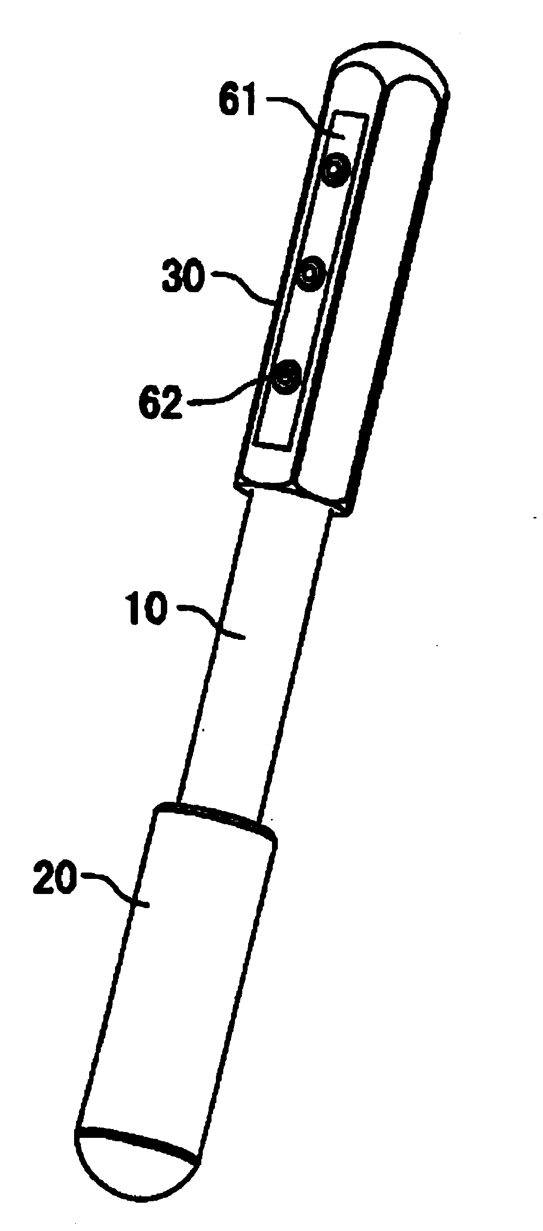
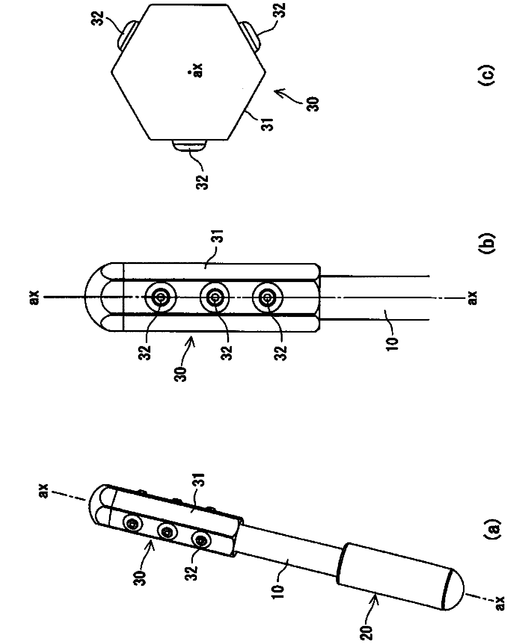
[0051] exist Figures 1 to 3 Among them, reference numeral 10 represents the handle held by the user. One end of the handle 10 is provided with a cooling rotor 20 for cooling the skin, and the other end of the handle 10 is provided with a roller 30. Both the cooling rotor 20 and the roller 30 can rotate. In the drawing, the symbol ax represents the rotation center of the rotor 20 for cooling and the roller 30 .

[0052] In the present invention, the cooling rotor 20 is not an essential part and can be omitted.

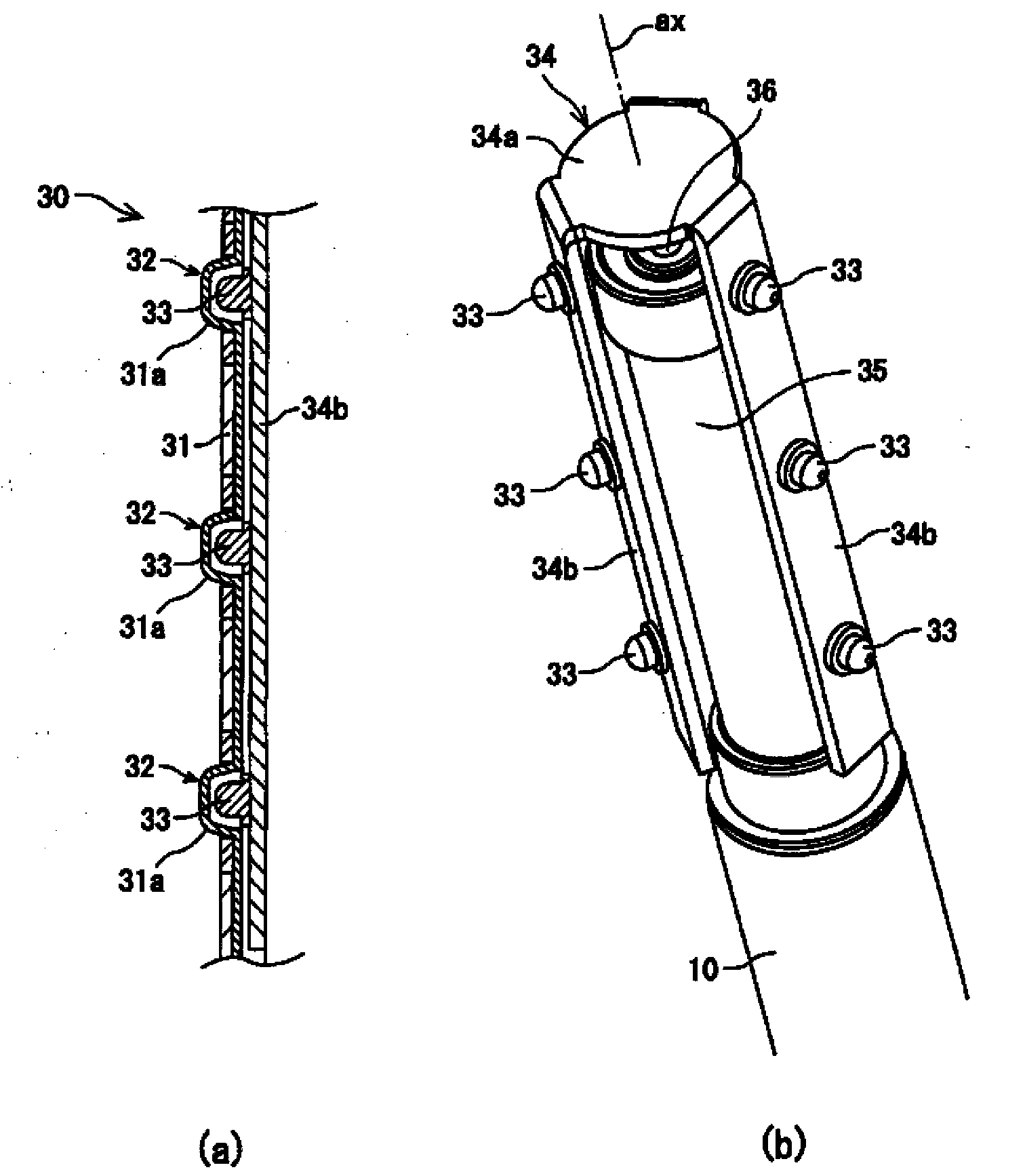
[0053] Reference numeral 31 denotes a hexahedral hollow column forming the outer skin of the roller 30 . The front end of the hexahedral hollow column 31 is closed to form a hemispherical shape. Reference numeral 32 denotes a light-emitting part installed in the hexahedral hollow column 31 , reference numeral 33 denotes a light-emitting diode LED installed in the light-emitting part 32 , and reference numeral 34 denotes a circuit board installed inside the hexahedral...

no. 2 approach

[0065] exist Figure 4 Among them, the symbol 37 is a touch switch, which is used to turn on and off the LED33 and the power supply, and the symbol 38 is a photoelectric conversion board used as a power supply. If there is current flowing between the two electrodes, the touch switch is in a conducting state at 37 .

[0066] The front part of the hexahedral hollow column 31 is made of a light-transmitting material on the photoelectric conversion board 38 and the LED 33 , and the front part of the touch switch 37 is made of a conductor (electrode).

[0067] The touch switch 37 is provided on the same side as the LED 33 . The side without LED33 is not provided with touch switch 37.

[0068] The touch switch 37 is connected to the LED 33 and the button battery 36 on the same side.

[0069] Therefore, when the roller 30 with a polygonal section is rotated on the skin, only when the LED 33 is in contact with the skin, the touch switch 37 is conducted through the user's body part ...

no. 3 approach

[0083] exist Figure 6 Among them, the number 11 is a cylindrical light guide shaft made of light-transmitting materials; the number 12 is a conical reflector with silver coating arranged inside the light guide shaft 11; the number 33 is an LED, which forms with the light guide shaft 11 Optical connection (luminescence of the LED can be emitted into the light guide shaft 11).

[0084] The light guide shaft 11 is equivalent to a structure formed by butt jointing of two semi-cylindrical bodies cut vertically from a cylindrical body. One end of the light guide shaft 11 is mounted on the handle 10 . A rotatable hexahedron hollow column 31 is provided outside the light guide shaft 11 , thereby constituting a roller 30 . In this way, the roller 30 is not only installed on the handle 10, but also can rotate.

[0085] In addition, the light emitting parts 32 located on multiple sides of the roller 30 are arranged so that when the roller 30 rolls, the moving tracks of each light emi...


PUM


Abstract

[Problem] When generating electricity by rotation of a roller to cause a light emitting part to emit light, the rotation of the roller became heavy due to the load thereof, causing the massaging feel to be dull. [Solution] A rod-shaped roller (30) with a polygonal cross section is rotatably joined to a handle (10) around an axis of rotation (ax) which runs along the longitudinal direction of the roller, and light emitting parts (32B-1 to 3, 32D-1 to 3, 32F-1 to 3) provided on side faces (31B, 31D, 31F) of the roller (30) are made to emit light by a built-in battery contained in the roller (30) or the handle (10). Iontophoresis is also possible by attaching iontophoresis electrodes to the sides of the roller and energizing them.

Description

technical field [0001] The invention relates to a skin beautifying roller device for skin care. The skin beautifying roller device has a rotatable roller, and photoelectric skin care mechanisms such as a light emitting part and an ion introduction electrode are built in the roller. When in use, the roller is pressed against the On the face or neck, push the roller to rotate, and use the rotation of the roller to stimulate the skin. At the same time, the light-emitting part performs light irradiation, and the electrode for ion introduction performs electrical stimulation to perform photoelectric care on the skin. Background technique [0002] Patent Document 1 discloses a skin beautifying roller device that uses the rotation of the roller to generate electricity from a built-in power generator, and drives the skin care mechanism with the generated power. [0003] Patent document: Japanese Patent Laid-Open No. 2008-264507 [0004] But utilize the rotation of roller to make ge...

Claims


Application Information

Patent Timeline
Patent Type & Authority Applications(China)
IPC IPC(8): A61H23/02A61N1/44A61N5/06
CPCA61H15/02A61N2005/0644A61H2015/0014A61N5/0616A61H7/003A61N2005/0651A61H15/0092A61N1/0428A61H2201/0214
Inventor 山崎岩男
Owner YA MAN LTD
Why Eureka
Try Eureka