Highly rigid complex machine

A composite processing, high rigidity technology, applied in metal processing machinery parts, metal processing equipment, manufacturing tools, etc., can solve the problems of low rigidity, long distance, weak rigidity, etc., to improve the overall rigidity, improve processing accuracy, reduce shaking Effect

Active Publication Date: 2014-01-01
DN SOLUTIONS CO LTD
View PDF9 Cites 6 Cited by
  • Summary
  • Abstract
  • Description
  • Claims
  • Application Information

AI Technical Summary

Problems solved by technology

[0009] However, in the conventional column-moving type compound processing machine, the machining axis (200') is located above the column (100'), and when the column (100') is moved to the high center of gravity (G), rolling (horizontal shaking) occurs. , rolling) and pitching (up and down shaking, pitching), due to the long distance between the center of gravity (G) of the column (100') and the Y-axis guide rail (Y1', Y2'), there is a loop (loop, in a stable vibration Or the pla

Method used


Image

  • Highly rigid complex machine
  • Highly rigid complex machine
  • Highly rigid complex machine

Examples


Embodiment Construction

[0040] Next, a high-rigidity compound processing machine according to an embodiment of the present invention will be described with reference to the drawings.

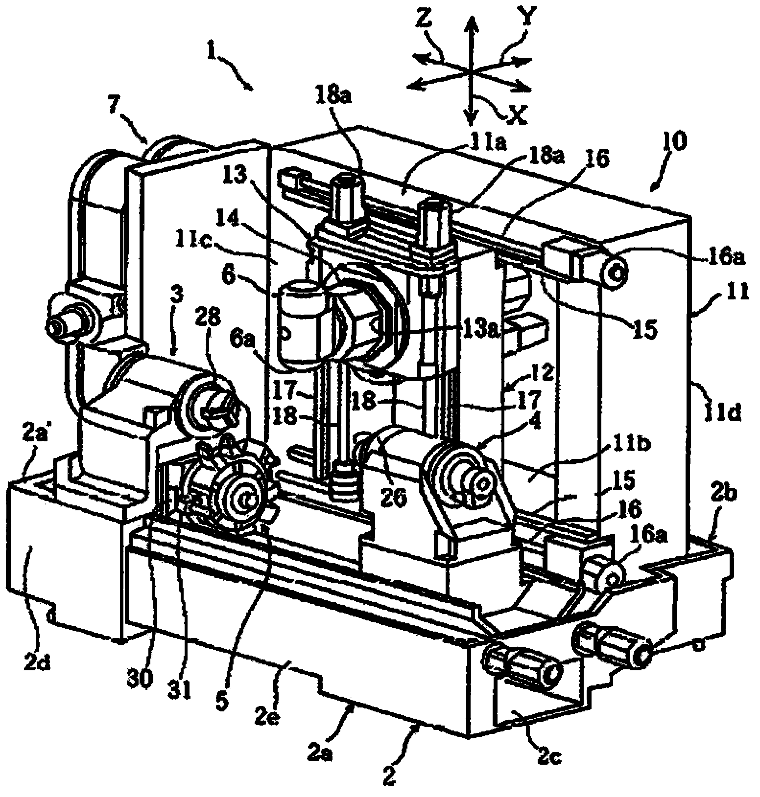
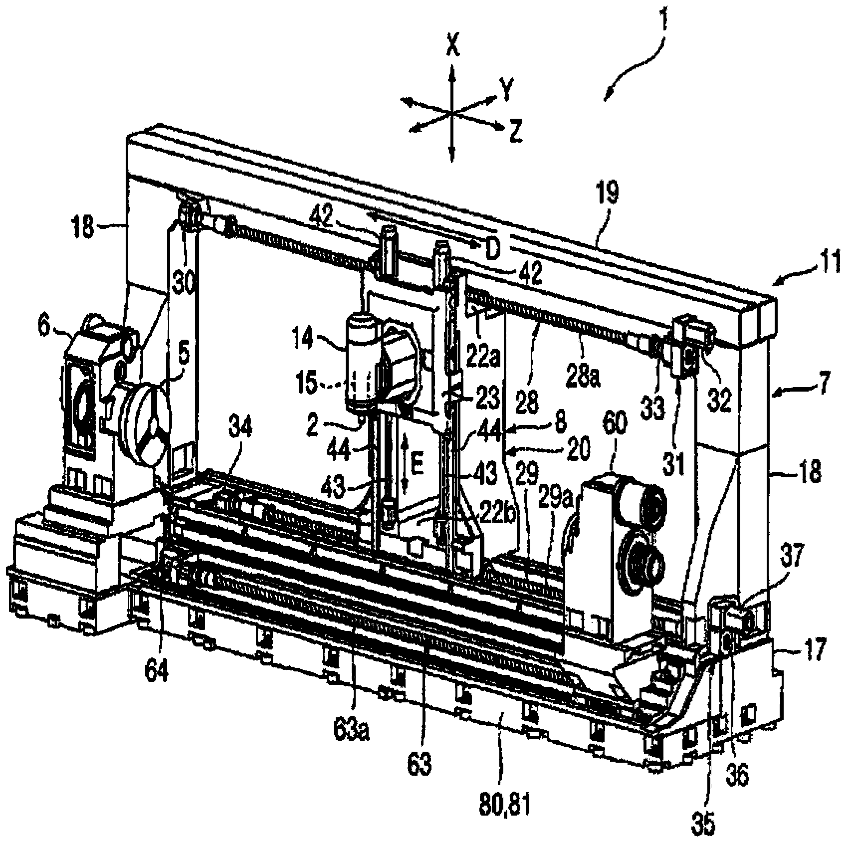
[0041] In the following description, the "longitudinal direction" refers to the left-right direction or the Z-axis direction when the multi-function processing machine is viewed from the front. The "vertical direction" means the vertical direction or the X-axis direction perpendicular to the Z-axis of the multifunctional processing machine. The "front-rear direction" is perpendicular to the Z-axis and the X-axis of the multifunctional processing machine and refers to the depth direction or the Y-axis direction when the multifunctional processing machine is viewed from the front.

[0042] Fig. 2 is a structural diagram of a high-rigidity compound processing machine according to an embodiment of the present invention.

[0043] As shown in Fig. 2, the compound processing machine of the embodiment of the present invention...


PUM


Abstract

The present invention relates to a highly rigid complex machine having a structure in which parts constituting a shaft are disposed adjacent to the central portion of a column to reduce rolling and pitching, and a stage is disposed on a saddle to improve rigidity. The highly rigid complex machine includes: a bed (400) on the top surface of which Z-axis guide ways (Z1, Z2) are formed in a lengthwise direction; a saddle (300) on which Y-axis guide ways (Y1, Y2) are formed in the front and rear directions perpendicular to the lengthwise direction, the bottom surface of the saddle (300) having a shape corresponding to that of the top surface of the bed (400) so as to be conveyed in the lengthwise direction of the bed (400); a column (100) on which X-axis guide ways (X1, X2) are formed in the vertical direction perpendicular to the length direction, the column (100) being disposed on the saddle (300) so as to be conveyed in the forward and rearward directions along the Y-axis guide ways (Y1, Y2); and a working shaft (200) disposed at a front side of the column (100) so as to ascend or descend along the X-axis guide ways (X1, X2). The Y-axis guide ways (Y1, Y2) are disposed at positions that are spaced a predetermined distance apart from a lower end of the column (100) in the upward direction.

Description

technical field [0001] Embodiments of the present invention relate to a composite processing machine, and more specifically, to a high-rigidity composite processing machine capable of reducing rolling and pitching by having a structure in which the shaft is brought close to the center of the column. ) and has a stepped structure at the saddle for increased rigidity. Background technique [0002] In general, a compound processing machine refers to a multi-spindle machine tool capable of both turning and milling, and can perform turning or milling depending on the type of tool attached to the spindle. [0003] This type of multi-function processing machine includes a three-axis linear transfer structure (X, Y, Z axis) and an axis (B axis) capable of tilting movement on the column in the height direction, and has a side for fixing the workpiece. Turning spindle. [0004] The driving method of the compound processing machine is divided into a ram moving method and a column mov...

Claims


Application Information

Patent Timeline
IPC IPC(8): B23P23/02B23B5/00B23C3/00B23Q1/70
CPCB23Q1/017B23P23/02B23B3/065
Inventor 河贤杓
Owner DN SOLUTIONS CO LTD
Why Eureka
Try Eureka