Hydrogen station

一种氢罐、压缩机的技术,应用在氢技术、气体/液体分配与储存、船只建造细节等方向,能够解决控制、设备庞大、氢站难温度等问题

Active Publication Date: 2014-01-01
KOBE STEEL LTD
View PDF11 Cites 10 Cited by
  • Summary
  • Abstract
  • Description
  • Claims
  • Application Information

AI Technical Summary

Problems solved by technology

[0013] However, both the "suction valve unloader method" and the "supplementary clearance method" are stepwise flow rate adjustments, so it is difficult to perform constant temperature control in the hydrogen station
[0014] In addition, regarding the "suction valve unloader method", a method has been proposed in which hydraulic control is combined with the suction valve unloader mechanism, and the capacity range of about 20 to 100% can be adjusted steplessly, but the equipment becomes bulky, etc. , is not practical

Method used


Image

  • Hydrogen station
  • Hydrogen station
  • Hydrogen station

Examples


no. 1 Embodiment approach )

[0028] figure 1 The configuration of the hydrogen station 1 according to the first embodiment of the present invention is shown. This hydrogen station 1 is configured such that, firstly, the reciprocating compressor on the low-pressure stage side (the low-pressure side reciprocating compressor: the first compression machine) 4 to supply hydrogen (hydrogen gas).

[0029] A drive machine 5 (such as an electric motor) is connected to the low-pressure side reciprocating compressor 4 via a drive shaft 5 a. The low-pressure side reciprocating compressor 4 is driven by the rotation of a drive shaft 5 a of a drive machine 5 . The driving machine 5 is an electric motor driven by an inverter. The drive machine 5 is capable of rotational speed control, that is, the drive shaft 5 a can be rotated at an arbitrary rotational speed. In addition, the driving machine 5 is not limited to a motor driven by an inverter as long as the rotational speed can be controlled.

[0030] The hydrogen ...

no. 2 Embodiment approach )

[0083] Figure 4 The configuration of the hydrogen station 1b according to the second embodiment of the present invention is shown. This hydrogen station 1b shares almost all of its configuration with the hydrogen station 1 related to the above-mentioned first embodiment. In addition, the same code|symbol is used for the same structure as said 1st Embodiment, and detailed description is abbreviate|omitted.

[0084] In the hydrogen station 1b of this embodiment, two intermediate pressure accumulators (the first intermediate pressure accumulator 9 and the second intermediate pressure accumulator 11) are provided, and the high pressure side reciprocating compression The machine 14 is different from the hydrogen station 1 of the first embodiment in that a flywheel 31 is provided on a drive shaft 15 a connected to the drive machine 15 . Furthermore, the hydrogen station 1b of the present embodiment is also different from the hydrogen station 1 of the first embodiment in that the ...

no. 3 Embodiment approach )

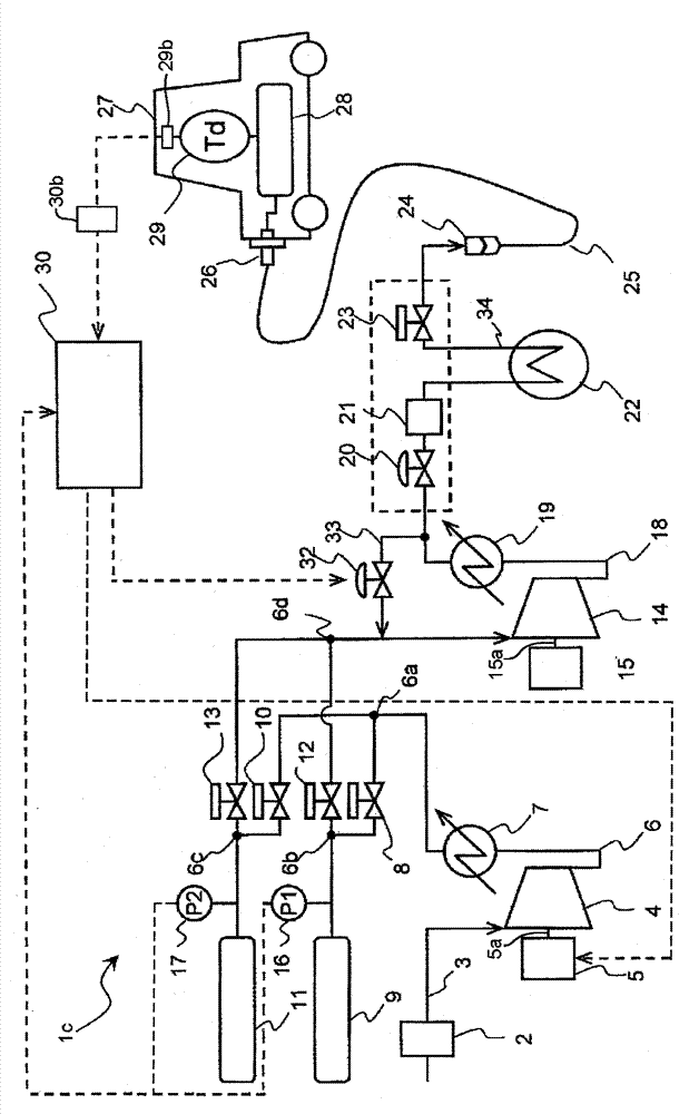
[0098] Figure 5 The configuration of a hydrogen station 1c according to a third embodiment of the present invention is shown. This hydrogen station 1c shares almost all of its configuration with the hydrogen station 1b related to the above-mentioned second embodiment. In addition, the same code|symbol is used for the same structure as said 2nd Embodiment, and detailed description is abbreviate|omitted.

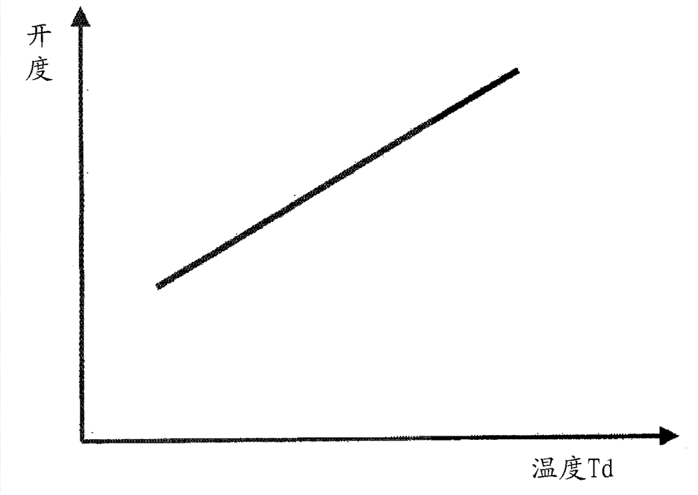
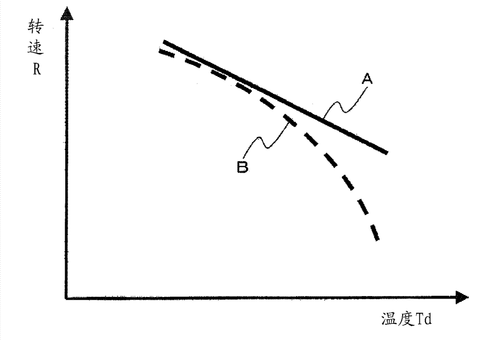
[0099] In the hydrogen station 1b of the second embodiment, the rotation speed of the driving machine 15 is controlled based on the temperature Td. On the other hand, in the hydrogen station 1b of the present embodiment, the opening degree of the adjustment valve 32, which will be described later, is adjusted based on the temperature Td. It is different in that the amount of hydrogen (return amount) returned from the discharge side to the suction side of the high-pressure side reciprocating compressor 14 via the return flow path 33 described later is adjusted.

[0100] In t...


PUM


Abstract

Provided is a hydrogen station for feeding hydrogen to an external hydrogen tank, the hydrogen station is characterized by comprising: a reciprocating compressor driven by a drive machine having a controllable rotational speed; a cooling device capable of cooling the hydrogen being fed from the reciprocating compressor to the hydrogen tank; a temperature sensor for detecting the temperature of the interior of the hydrogen tank or the temperature of the hydrogen being fed to the hydrogen tank; and a control unit for controlling the rotational speed of the drive machine on the basis of the temperature detected by the temperature sensor.

Description

technical field [0001] The present invention relates to a hydrogen station for supplying hydrogen to fuel cell vehicles, hydrogen fuel vehicles, and the like. Background technique [0002] Recently, there are concerns about global warming and air pollution caused by carbon dioxide (CO2), nitrogen oxides (NOX), and suspended particulate matter (PM) contained in automobile exhaust gases. Therefore, a fuel cell vehicle (FCV) driven by electric energy based on a chemical reaction of hydrogen and oxygen contained in a fuel cell instead of a conventional gasoline internal combustion vehicle has attracted attention. [0003] Fuel cell vehicles do not emit the above-mentioned carbon dioxide, etc., nor do they emit other harmful substances. In addition, fuel cell vehicles have various advantages that gasoline internal combustion vehicles do not have, such as better energy efficiency than gasoline internal combustion vehicles. [0004] However, in fuel cell vehicles, there are rough...

Claims


Application Information

Patent Timeline
Patent Type & Authority Applications(China)
IPC IPC(8): F17C5/06F17C13/02
CPCF17C2221/012F17C2270/0139F17C5/06F17C2227/0337F17C2250/01F17C2227/0388F17C2225/036F17C2225/0123F17C5/007F17C2260/023F17C2223/033Y02E60/321F17C2223/0123F17C2205/0326F17C2205/0338F17C13/026F17C2250/0443Y02E60/324F17C2227/0164F17C2227/0185F17C2250/032F17C13/02F17C2250/0439F17C2250/043F17C2265/065Y02P90/45Y02E60/32
Inventor 名仓见治高木一
Owner KOBE STEEL LTD
Why Eureka
Try Eureka