
Feeding and discharging device of pipe straightener

A technology for straightening machines and steel pipes, applied in the direction of feeding devices, positioning devices, storage devices, etc., can solve problems such as failure to meet normal production requirements, high labor intensity of manual stacking, and failure of straightening output by straightening machines. Avoid damage such as friction and collision, improve production efficiency, and improve the effect of straightening quality

Inactive Publication Date: 2014-01-08
天津腾飞钢管有限公司
View PDF0 Cites 2 Cited by
  • Summary
  • Abstract
  • Description
  • Claims
  • Application Information

AI Technical Summary

Problems solved by technology

In actual use, there are the following problems: the straightened profiles need to be transferred from the output roller table of the straightening machine to the collection platform through the steel dial mechanism. The steel dial mechanism is driven by an air cylinder. The machine cannot straighten the output, which reduces the utilization rate of the straightening machine and affects the production efficiency; due to the heavy weight of a large-scale single finished profile, after being transported to the bundling stand, the labor intensity of manual stacking is very high, and the labor productivity is low. Unable to meet normal production requirements

Method used


Image

  • Feeding and discharging device of pipe straightener
  • Feeding and discharging device of pipe straightener
  • Feeding and discharging device of pipe straightener

Examples


Embodiment Construction

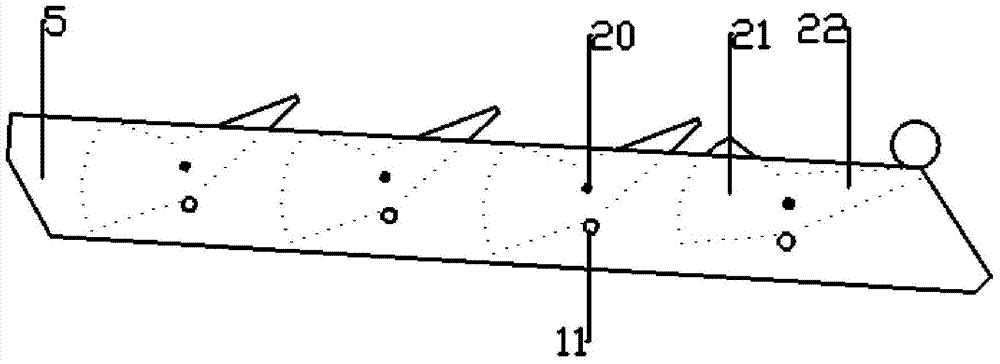
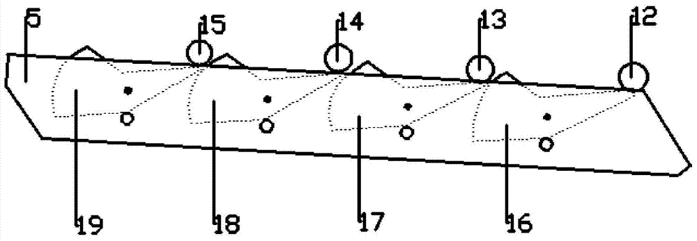
[0020] Such as figure 1 As shown, a loading and unloading device for a steel pipe straightening machine includes an inlet guide cylinder 1, a straightener 2, an upper outlet guide cylinder 3, an output roller table 4, and a stand 5, and the inlet guide cylinder 1 is located at the The front end of the straightening machine 2, the upper and lower inner walls are connected with spray water drains; the upper outlet guide cylinder 3 and the output roller table 4 are located at the rear end of the straightening machine 2, and the upper The rear end of the outlet guide cylinder 3 and the output roller table 4 is provided with a baffle plate 6; the described stand 5 is located at the lower end of the output roller table 4; the upper outlet guide cylinder 3 is located at the The upper end of output roller table 4, its inner wall is provided with more than one air blower 7.

[0021] Further, the spray water row includes a guide tube 8, a spray port 9, and a return port 10, and the ret...


PUM


Abstract

The invention provides a feeding and discharging device of a pipe straightener. The feeding and discharging device comprises an inlet guide barrel, the straightener, an upper outlet guide barrel, an output roller way, and a table frame. The inlet guide barrel is located at the front end of the straightener. The upper inner wall and the lower inner wall of the inlet guide barrel are connected with mist spray water rows. The upper outlet guide barrel and the output roller way are located at the back end of the straightener. Baffles are arranged at the back end of the upper outlet guide barrel and the back end of the output roller way. The table frame is located at the lower end of the output roller way. More than one blower is arranged on the inner wall of the upper outlet guide barrel. Due to the further arrangement of the mist spray water rows and the blowers, the temperature of steel pipes in front of the straightener and the temperature of steel pipes behind the straightener are reduced, straightening quality is improved, and deformation after straightening is reduced. The baffles prevent straightened steel pipes from coming off the roller way. A spiral roller is adopted for the output roller way and enables the straightened steel pipes to go straightly on the output roller way and deviate toward the table frame at the same time, so that production efficiency is improved, and the effects of saving energy and reducing consumption are achieved. A tumbler type baffle mechanism is simple in structure, light in weight, and capable of separating steel pipes one by one, so that friction collisions caused at rolling time of the steel pipes are avoided.

Description

technical field [0001] The invention relates to the technical field of steel pipe processing equipment, in particular to a loading and unloading device of a steel pipe straightening machine. Background technique [0002] In fast-paced production, the actual temperature of the steel pipe after straightening is generally much higher than the required straightening temperature, and the steel packaging is generally bound by buckling on both sides, and then hoisted and squeezed many times during storage and transportation. Therefore, when the user uses it, some steel may be deformed after being rolled off the production line due to the high temperature after straightening; the existing loading and unloading device for the straightening machine is generally hoisted by the crane to the loading material in the form of random bundles. On the platform, after manual combing, the single profile to be straightened is transferred to the input roller table of the straightening machine thro...

Claims


Application Information

Patent Timeline
Patent Type & Authority Applications(China)
IPC IPC(8): B21D37/16B21D43/26B21D43/08B21D45/00B21D3/00
Inventor 刘学贤
Owner 天津腾飞钢管有限公司
Learn More