Hovercar

A flying car and body technology, applied in the field of flying cars, to achieve the effect of good endurance performance and little aerodynamic interference

Inactive Publication Date: 2014-01-08
赵辉
View PDF9 Cites 20 Cited by
  • Summary
  • Abstract
  • Description
  • Claims
  • Application Information

AI Technical Summary

Problems solved by technology

[0007] The further technical problem to be solved in the present invention is to solve th

Method used


Image

  • Hovercar
  • Hovercar
  • Hovercar

Examples


Embodiment 1

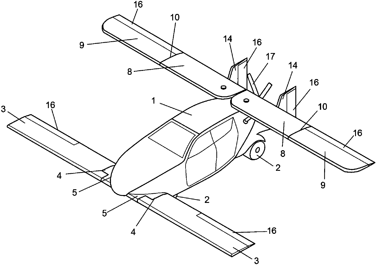
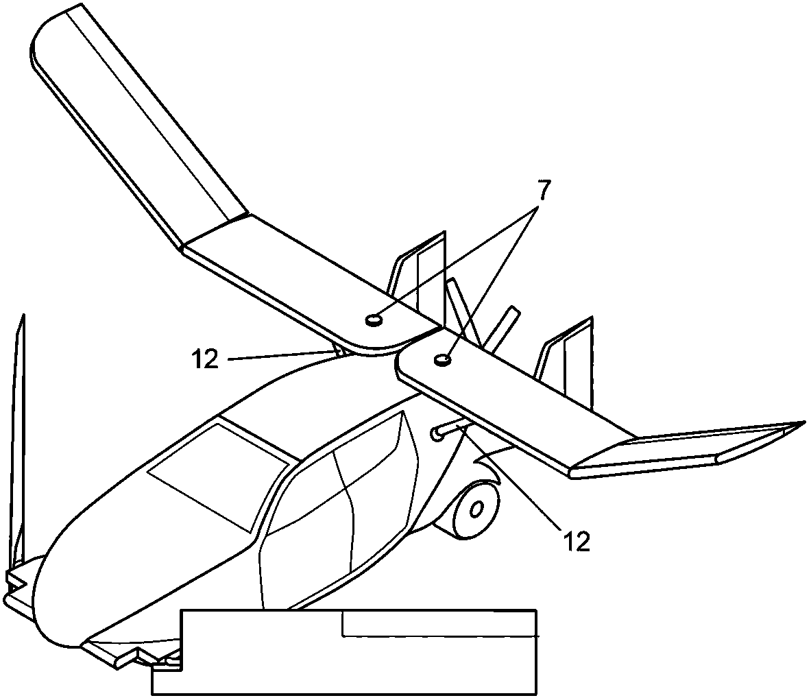
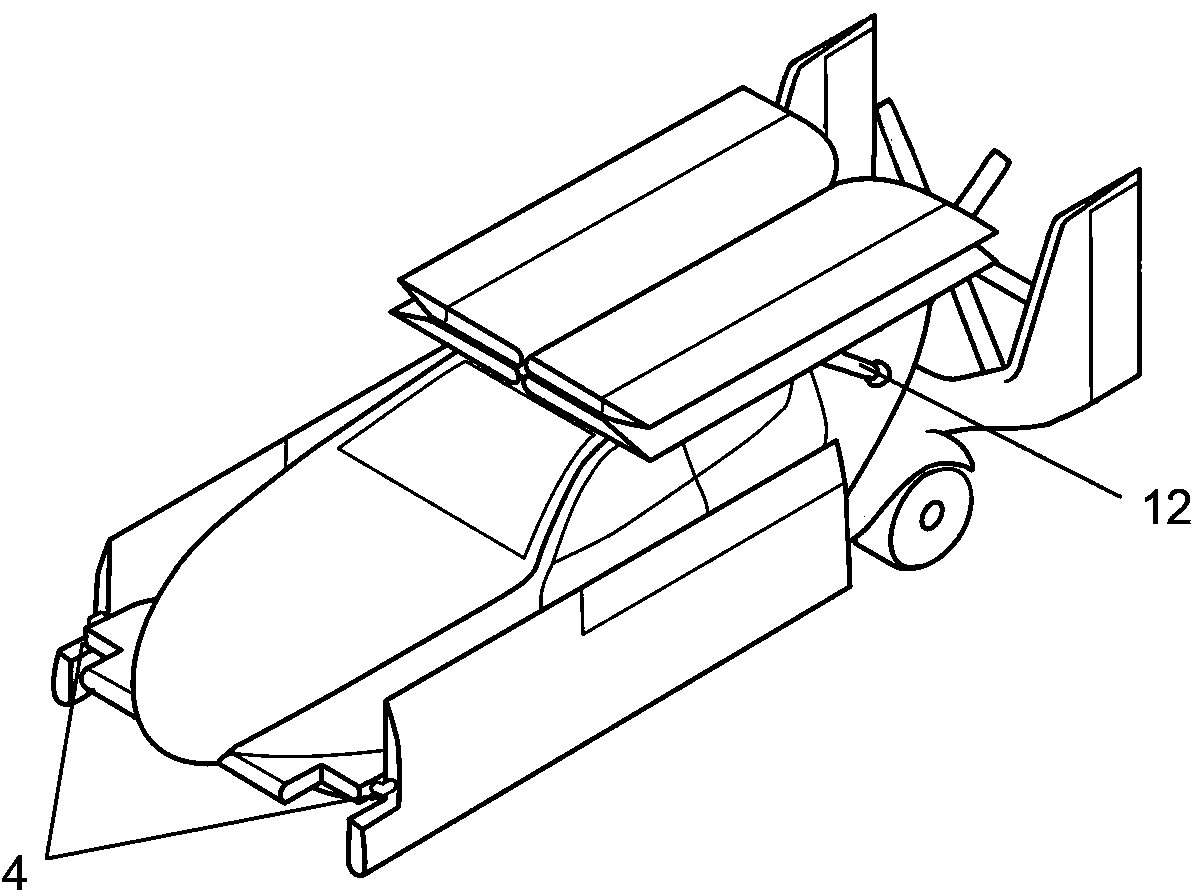
[0043] See attached figure 1 , 2 , this flying car comprises parts such as body 1, front wing 3, rear wing 6, propeller 17, wheel 2, vertical tail 14, and the both sides of front part of body 1 is a pair of front wing 3 that can be flipped and folded, and the body 1 There are two reversible and foldable rear wings 6 on both sides of the rear part, and the wing roots of a pair of front wings 3 are movably connected to the front wing frames 5 on both sides of the front part of the vehicle body 1 through the front wing connecting device 4 respectively, The wing roots of a pair of rear wings 6 are movably connected with the vertical shafts on both sides of the rear upper side of the vehicle body 1 through the rear wing connection device 7 respectively, and the rear wing inner wing 8 and the rear wing outer wing 9 are through the interwing hinge folding device 10 connect. These two pairs of wings form a front-rear tandem double-main-wing aerodynamic layout along the body 1, whic...

Embodiment 2

[0058] The present embodiment is an amphibious flying car, and the comprehensive performance of water, land and air is balanced to meet the needs of people living in seaside or river and lake areas.

[0059] See attached Figure 5 , 6 A tilted nacelle 18 is respectively installed on the left and right sides of the front portion of the vehicle body 1, and each tilted nacelle 18 is respectively equipped with a propeller 17 for providing the pulling force required for flight. The propeller 17 is installed in the higher position of the front part of the vehicle body 1, at a certain height from the water surface, and is protected by the front wing 3 at the front bottom, so as to prevent the propeller 17 from being damaged by splashing water. The propellers on both sides cancel each other's torque as they spin. The bottom of the body 1 is a V-shaped bottom with a ramp angle, and the wheels 2 adopt the wheel turning and lifting technology currently used on high-speed amphibious veh...

Embodiment 3

[0067] See attached Figure 7 , a coaxial double-propeller vertical take-off and landing ducted thruster 23 is installed on the front of the vehicle body 1 to provide vertical downward thrust. The propellers rotate in the horizontal plane without generating torque to the vehicle body 1. The upper cover plate 24 hingedly connected with the vehicle body 1 is provided with an array of parallel multi-piece guide vanes 25 at the exhaust port, and the array of guide vanes 25 is movably connected with the vehicle body 1 . The multi-piece deflector 25 array can be deflected to realize the control of the roll attitude in flight. When flying horizontally, the upper cover plate 24 of the air inlet of the duct and the array of deflectors 25 of the air outlet are deflected, basically covering the duct opening, sealing the vehicle body 1, and reducing flight resistance.

[0068] Two side-by-side single screw propellers are installed at the rear of the car and can tilt the ducted propeller ...


PUM

PropertyMeasurementUnit
Spanaaaaaaaaaa
Chord lengthaaaaaaaaaa
Areaaaaaaaaaaa

Abstract

The invention discloses a hovercar with folding wings, wherein the hovercar is in a serial aerodynamic layout. The hovercar comprises a hovercar body, wheels installed on the lower portion of the hovercar body, main wings which are installed on the two sides of the hovercar body and can produce upward lift force and a propeller which is installed on the hovercar body and can produce push force. The front wings and the rear wings are all the main wings with large wing areas and long wingspans. When the wings of the hovercar are unfolded, the front wings and the rear wings constitute a longitudinal serial aerodynamic layout along the hovercar body and together produce upward lift force. When the wings of the hovercar are folded, the front wings are turned and folded to be on the two sides of the hovercar body, and the rear wings are turned and folded to be on the top of the hovercar body or the two sides of the hovercar body. The surfaces of the wings and the surface of the hovercar body are provided with large-area solar cell panels, the whole car becomes a large solar charger, and the endurance is improved. The invention further provides a hovercar vertically taking off and landing and a hovercar capable of being used in water, on land and in air on the basis of the hovercar.

Description

technical field [0001] The invention relates to a vehicle, in particular to a flying car. Background technique [0002] Combining the two means of transportation, automobiles and airplanes, is an idea that has been around for a long time. So far, there have been many flying car schemes and some real products at home and abroad, most of which have various design defects. For example, the Terrafugia flying car in the United States and the flying car of Moulton Taylor can only be called folding-wing aircraft that can travel on roads. Several domestic and foreign patents that are most similar to the present invention, such as US Patent No. US6619584B11, a patent named "ROAD / AIR VEHICLE" discloses a flying car, and the Chinese patent application number is CN201110047409.5, and the publication date is 2011 On July 27, 2010, a patent titled "Flying Car" disclosed a flying car. Both flying cars adopted an aerodynamic layout with canards installed on the front of the body and main ...

Claims


Application Information

Patent Timeline
IPC IPC(8): B60F5/02B60L8/00
CPCB64C37/00Y02T10/7083B60F5/02B64D2211/00Y02T10/7072Y02T50/50
Inventor 不公告发明人
Owner 赵辉
Why Eureka
Try Eureka