Automatic feeding and discharging system for pipe fitting machining device

A technology of automatic loading and unloading, processing machine, applied in the direction of conveyor objects, packaging, loading/unloading, etc., can solve the problems of low work efficiency, low efficiency, complicated operation, etc., to achieve the effect of simple structure and improved processing efficiency

Active Publication Date: 2014-01-08
广州捷晟自动化控制设备有限公司
View PDF6 Cites 13 Cited by
  • Summary
  • Abstract
  • Description
  • Claims
  • Application Information

AI Technical Summary

Problems solved by technology

[0004] Most of the existing pipe fitting processing machines are manually loaded and unloaded (the workpiece is manually placed in the holder, and then manually taken out after processing), and the operation is complicated. High risk and low efficiency
[0005]There are a small number of pipe end machines equipped with automatic loading and unloading mechanisms, but most of them have complex structures, high failure rates, and inconvenient debugging
Loading and unloading are completed in two separate steps, and the work efficiency is very low. Although some loading and unloading are carried out at the same time, the structure is complicated and requires several actions to complete, so the work efficiency is not high.

Method used


Image

  • Automatic feeding and discharging system for pipe fitting machining device
  • Automatic feeding and discharging system for pipe fitting machining device

Examples


Embodiment Construction

[0028] The present invention will be further described below in conjunction with the accompanying drawings and embodiments.

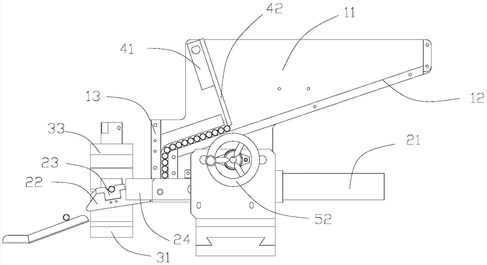
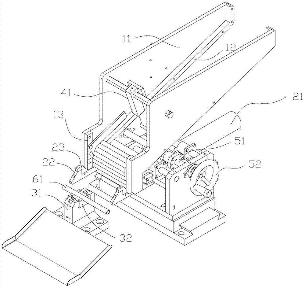
[0029] Such as figure 1 and figure 2 As shown, an automatic loading and unloading system of a pipe fitting processing machine includes a hopper, a push device and a clamping device; the hopper is located above the push device, and a guide track for the pipe fittings to pass is arranged in the hopper; the clamping device is located in front of the push device, The clamping device comprises a lower clamping die 31 and an upper clamping die 33, and the lower clamping die 31 is provided with a second groove for placing pipe fittings; The push rod pushes forward to make the pipe placed in the first groove be located in the second groove position of the clamping device and the power device 21 that retracts the push rod backward, the power device 21 can be constituted by a feeding cylinder. The front end of the push rod is provided with a slope for pushing ...


PUM


Abstract

The invention discloses an automatic feeding and discharging system for a pipe fitting machining device. The automatic feeding and discharging system for the pipe fitting machining device comprises a hopper, a pushing device and a clamping device. The hopper is arranged above the pushing device, and a guiding track where pipe fittings pass is arranged in the hopper. The pushing device comprises a pushing rod of a first groove where the pipe fittings are placed and a power device, the power device pushes the pushing rod forward to enable the pipe fittings in the first groove to be arranged at the position of a second groove of the clamping device and enables the pushing rod to retract back, and the power device can be composed of a feeding air cylinder. A slope used for pushing the pipe fittings in the second groove to be out of the clamping device is arranged at the front end portion of the pushing rod. The tail end of the guiding track is arranged above the first groove of the pushing device. Due to the fact that the slope is arranged at the front end of the pushing rod, when the pushing rod carries out forward pushing, the machined pipe fittings arranged in a lower clamping die can be pushed out of the second groove and are replaced by new pipe fittings to be machined, one pushing action can finish the actions of feeding and discharging, and the automatic feeding and discharging system for the pipe fitting machining device is simple in structure and improves machining efficiency.

Description

[0001] technical field [0002] The invention relates to an automatic loading and unloading system, in particular to an automatic loading and unloading system of a pipe fitting processing machine. [0003] Background technique [0004] Most of the existing pipe fitting processing machines are manually loaded and unloaded (the workpiece is manually placed in the holder, and then manually taken out after processing), which is complicated to operate, high in risk, and low in efficiency. [0005] There are a small number of pipe end machines equipped with automatic loading and unloading mechanisms, but most of them have complex structures, high failure rates, and inconvenient debugging. Loading and unloading are completed in two separate steps, and the work efficiency is very low. Although some loading and unloading are carried out at the same time, the structure is complex and requires several actions to complete, so the work efficiency is not high. [0006] Contents ...

Claims


Application Information

Patent Timeline
Patent Type & Authority Applications(China)
IPC IPC(8): B65G47/82B65G47/90B65G65/44B65D88/66
Inventor 祝金波
Owner 广州捷晟自动化控制设备有限公司
Why Eureka
Try Eureka