
Anchoring method of flat cross section of carbon fiber composite reinforcement material

A technology of composite materials and anchoring methods, which is applied in the direction of structural elements, building components, building reinforcements, etc., can solve the problems of unfavorable anchoring, raising, and small thickness of rib protrusions, etc., so as to avoid inconsistency of perfusion, high anchoring efficiency, and reduce small length effect

Active Publication Date: 2014-01-08
FASTEN HONGSHENG GRP CO LTD
View PDF7 Cites 8 Cited by
  • Summary
  • Abstract
  • Description
  • Claims
  • Application Information

AI Technical Summary

Problems solved by technology

[0003] One: The surface of carbon fiber composite reinforcement is smooth, which is not conducive to anchoring. Although there are some carbon fiber composite reinforcement with ribs on the surface, the thickness of the rib protrusions is small, which has a limited effect on improving the anchoring performance, and the ribbed composite The process of material reinforcement is more complicated
[0004] Second: the length of the anchoring bond is not enough during anchoring, which can easily cause slippage between the carbon fiber composite material and the anchoring filler
Although some methods realize the bonding and anchoring of carbon fiber composite reinforcement, the anchoring bond length is too long, which is not conducive to the increase of the tonnage of the anchor barrel, and the engineering practicability is not strong
[0005] Third: Some anchoring fillers have poor fluidity. When anchoring carbon fiber composite reinforcement, it will increase the difficulty of pouring anchor fillers, which will easily lead to incomplete pouring and decrease the anchoring strength.

Method used


Image

  • Anchoring method of flat cross section of carbon fiber composite reinforcement material
  • Anchoring method of flat cross section of carbon fiber composite reinforcement material

Examples


Embodiment Construction

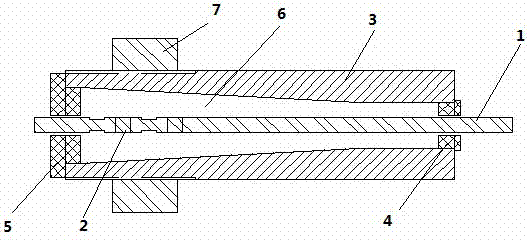
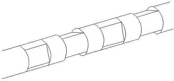
[0017] see figure 1 with figure 2 , figure 1 It is a longitudinal section structure drawing of the bonded anchoring scheme of the present invention. figure 2 It is a partial enlarged view of the three-dimensional entity of the rolled part of the carbon fiber composite material bar of the present invention. Depend on figure 1 with figure 2 It can be seen from the figure that the carbon fiber composite reinforcement is locally heated and softened near the end of the anchorage. When it is close to the curing temperature of the reinforcement, the heated part is rolled with a tool, and the rolled part becomes flat. A total of one reinforcement Carry out four times of rolling, alternately rolling twice in the orthogonal and vertical directions, and after cooling, the rolled parts are solidified again.

[0018] After passing the reinforcement through the positioning hole of the end plug and the cover, place the anchor vertically, remove the end plug, pour the prepared epoxy r...


PUM


Abstract

The invention relates to an anchoring method of a flat cross section of a carbon fiber composite reinforcement material. The anchoring method is characterized in that the carbon fiber composite reinforcement material is locally heated and softened at a part close to the tail of an anchorage device, when the temperature of the carbon fiber composite reinforcement material is close to the solidifying temperature of the reinforcement material, the heated part is rolled to be flat by a tool, the reinforcement material is subjected to four-times rolling, the rolling is respectively carried out two times in the orthogonal direction and the vertical direction of the reinforcement material, and after cooling, the rolled part is solidified again; after the reinforcement material passes through location holes of an end plug and a sealing cover, the anchorage device is vertically placed, the end plug is moved away, and an epoxy resin mortar anchoring filler is poured into the anchorage device from the small end of the anchorage device, after the anchorage device is filled with the filler, the end plug is put at an original location, and after the anchorage device is vertically placed for one day and the epoxy resin mortar anchoring filler is solidified, the glue pouring and solidifying of the other end are carried out. The anchoring method has the advantages that the local surface of the carbon fiber composite reinforcement material can be rapidly and conveniently flattened, the contact area between the reinforcement material and the epoxy resin mortar anchoring filler is enlarged, the mechanical bite force is generated, the anchorage bonding length is reduced, and meanwhile, the reinforcement material is prevented from slipping off from the anchoring filler.

Description

technical field [0001] The invention relates to an anchoring method for carbon fiber composite reinforcement. Especially the bonded anchoring method for anchoring carbon fiber composite reinforcement. Background technique [0002] The traditional anchoring system uses high-strength steel wire as the prestressed tendon. Due to the poor fatigue and corrosion resistance of steel, it is prone to rust and fatigue, which seriously affects the durability and safety of the anchorage structure. Carbon fiber composite materials have excellent properties such as light weight, high strength, no rust, corrosion resistance, fatigue resistance, low thermal expansion coefficient, and good shock absorption performance. Using carbon fiber composite material tendons as prestressed tendons can fundamentally solve the problem of steel fatigue resistance and durability. The problem of poor corrosion performance. However, carbon fiber composite reinforcement is a transversely isotropic material ...

Claims


Application Information

Patent Timeline
Patent Type & Authority Applications(China)
IPC IPC(8): E04C5/12E04C5/07E04C5/08
Inventor 朱元林刘礼华张继文宁世伟
Owner FASTEN HONGSHENG GRP CO LTD
Learn More