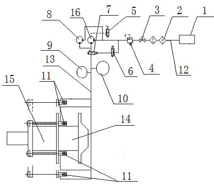
Hydraulic lock system
A hydraulic, gas-liquid pressurization technology, applied in the direction of fluid pressure actuating devices, etc., can solve the problems of shutdown and production, large economic losses, danger, etc.
- Summary
- Abstract
- Description
- Claims
- Application Information
AI Technical Summary
Problems solved by technology
Method used
Image
Examples
Embodiment Construction
[0012] like figure 1 As shown, the hydraulic locking system includes a filter 2, a manual stop valve 3, a pressure reducing valve 4, an electromagnetic reversing valve 6, an air control reversing valve 7, a first gas-liquid booster pump 8, and a pressure transmitter 10 And hydraulic locking cylinder 11, filter 2, manual stop valve 3 and pressure reducing valve 4 are connected with the first gas-liquid booster pump 8 through instrument air pipeline 12, air control reversing valve 7, pressure transmitter 10 and The hydraulic locking cylinder 11 is connected with the first gas-liquid booster pump 8 through the hydraulic oil pipeline 13, the electromagnetic reversing valve 6 is connected on the pipeline between the instrument air pipeline 12 and the hydraulic oil pipeline 13, and the hydraulic locking cylinder 11 is The cloth is installed around the water chamber 14 of the granulator 15, the lower end of the pressure transmitter 10 on the hydraulic oil pipeline 13 is provided with...
PUM
 Abstract
Description
Claims
Application Information
 - R&D
- Intellectual Property
- Life Sciences
- Materials
- Tech Scout
- Unparalleled Data Quality
- Higher Quality Content
- 60% Fewer Hallucinations
Browse by: Latest US Patents, China's latest patents, Technical Efficacy Thesaurus, Application Domain, Technology Topic, Popular Technical Reports.
© 2025 PatSnap. All rights reserved.Legal|Privacy policy|Modern Slavery Act Transparency Statement|Sitemap|About US| Contact US: help@patsnap.com

