An electric hand rubbing bionic device

A two-handed, electric technology, applied in the direction of transmission, electromechanical devices, electric components, etc., can solve the problems of high cost, high cost, complex structure, etc., and achieve the effects of high work reliability, widespread use and simple structure.

Inactive Publication Date: 2016-08-24
SUZHOU ROARING PRECISION MASCH CO LTD
View PDF10 Cites 0 Cited by
  • Summary
  • Abstract
  • Description
  • Claims
  • Application Information

AI Technical Summary

Problems solved by technology

This not only makes the whole device extremely large and complex, but also extremely expensive
For example, the kneading massager disclosed in Chinese patent document CN 102940566 A is not only extremely complicated in structure, but also fails to give the trajectory of bionic motion; another example is the numerically controlled rubbing type grinding machine disclosed in Chinese patent document CN 103252709 A, which uses three servo The motor, as well as the extremely complex mechanical transmission system, is bulky and expensive
From a kinematic point of view, no substantial hands-rubbing bionic device has yet been retrieved

Method used


Image

  • An electric hand rubbing bionic device
  • An electric hand rubbing bionic device

Examples


Embodiment 1

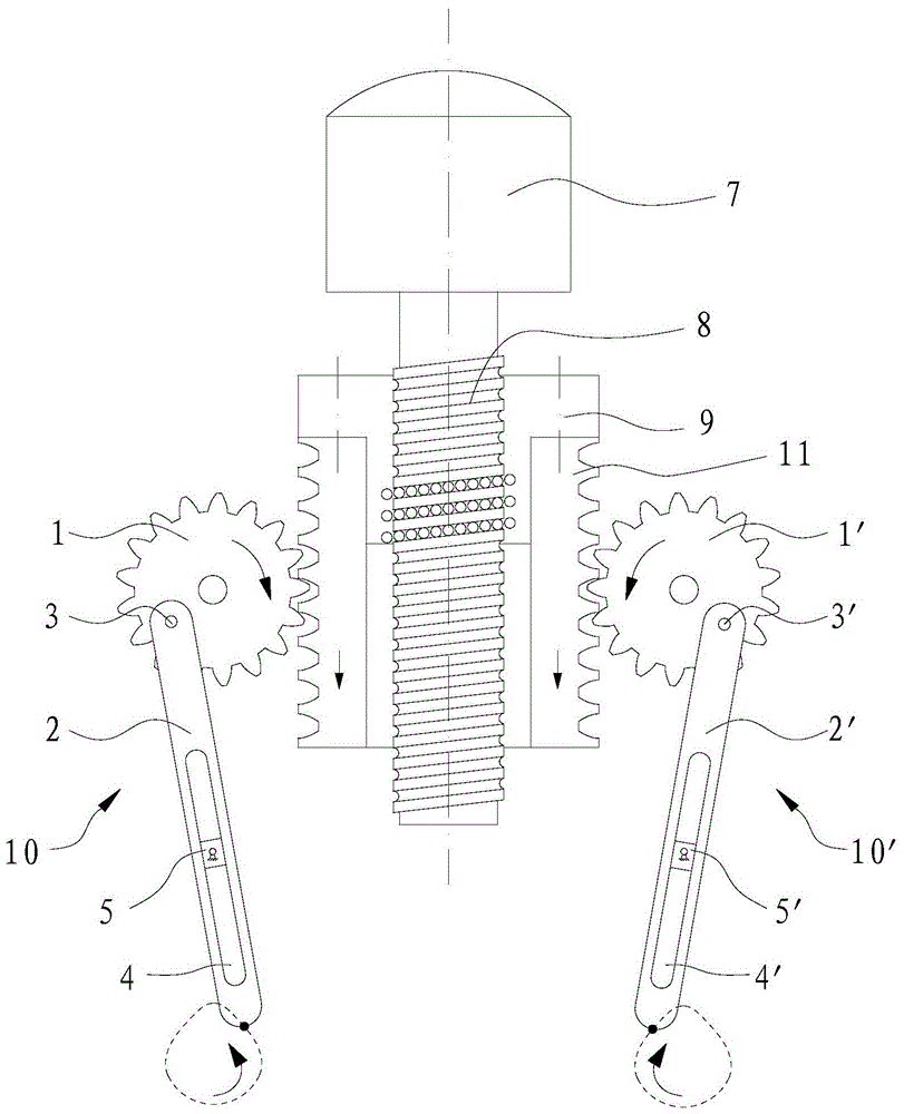
[0020] see picture 1 An electric hands rubbing bionic device shown, including a frame (not shown in the figure), two sets of rubbing components arranged on the frame 10 、 10’ 。

[0021] kneading components 10 Consists of gears rotatably arranged on the frame around the axis 1 , through the pin 3 rotatably set on the gear 1 connecting rod 2 . gear 1 There is an eccentric pin hole on the top, the center line of the pin hole is parallel to the gear 1 axis, pin 3 one end connected to the connecting rod 2 The upper part, the other end of which is rotatably passed through the above-mentioned pin hole. link 2 There is a chute on the top 4 , the chute 4 along the connecting rod 2 Extending in the length direction, the frame is provided with a central hinge on the frame to provide linkage 2 guide slider 5 , the slider 5 The center position of the two axial ends of the hinge is hinged on the frame, and the slider 5 It can be r...

Embodiment 2

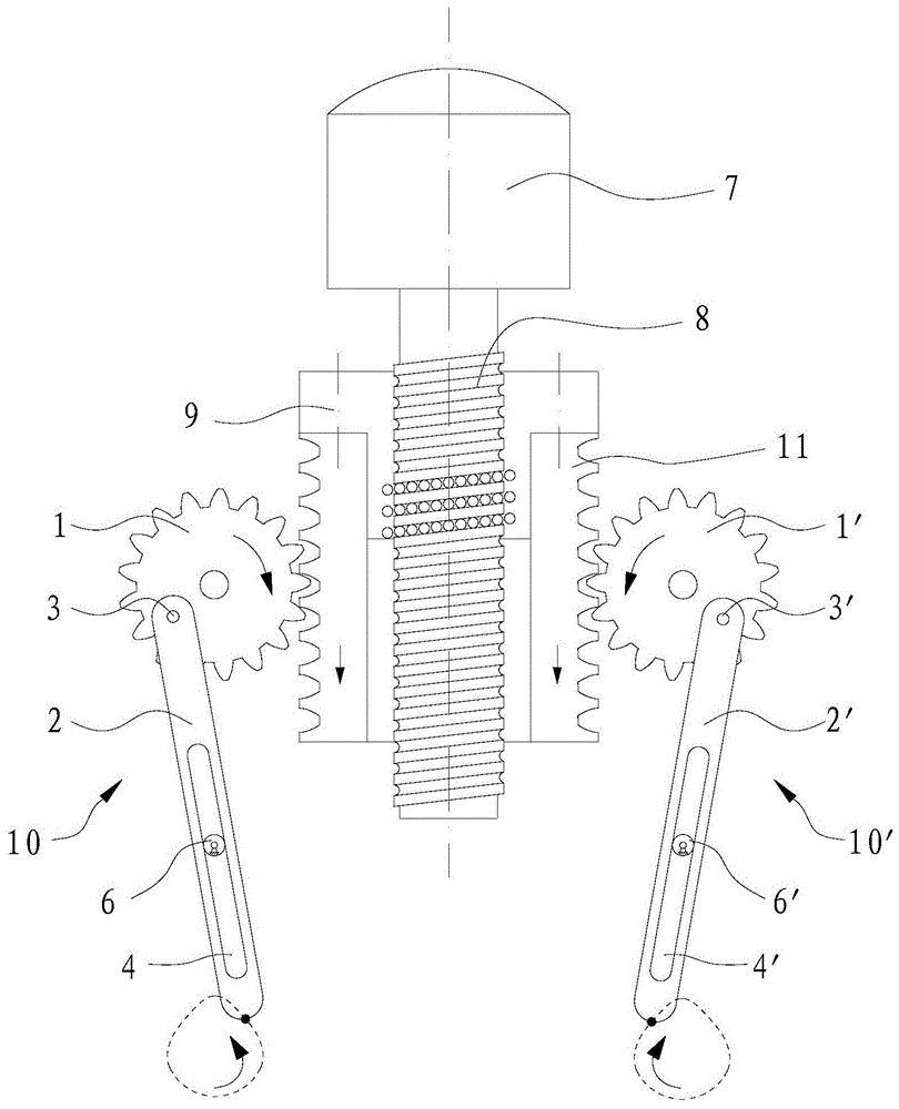
[0029] see picture 2 A kind of electric hands rubbing bionic device shown, this bionic device and embodiment 1 The difference is mainly in the provision of connecting rod 2 、 2’ Settings for the oriented widget. In this embodiment, a connecting rod is provided 2 、 2’ The guiding part is the guide fixedly set on the frame as the center 6 、 6’ , the guide 6 、 6’ respectively set in the chute with clearance fit 4 、 4’ middle, guide 6 、 6’ Upper and chute 4 、 4’ The circumferential outer surface matched with the groove wall in the length direction is a cylindrical surface, and the guide piece 6 、 6’ respectively with chute 4 、 4’ Form a plane high pair. double sided rack 11 Moves along the length while driving the gear 1 ,gear 1’ When rotating, the connecting rod 2 、 2’ pin 3 、 3’ The guide relative to the cylindrical outer surface under the action of 6 、 6’ Both linear motion and swing, so that the connecting rod 2 、 2’ The l...

Embodiment 1

[0032] Example 1 In the unilateral kneading action in Kinematics, there is only 5 a substantial moving component, the lead screw 8 , nut 9- double sided rack 11 Assemblies, gears 1 ( 1’ ),link 2 ( 2’ ), slider 5 ( 5’ ); Example 2 In the unilateral kneading action in Kinematics, there is only 4 a substantial moving component, the lead screw 8 , nut 9- double sided rack 11 Assemblies, gears 1 ( 1’ ),link 2 ( 2’ )。


PUM


Abstract

The invention discloses an electric hands-rubbing bionic device, in which only very simple lead screws, nuts, double-sided racks, gears, connecting rods, sliders whose centers are hinged on the frame or centers fixed on the frame are used. The guide piece on the cylindrical outer surface realizes the complex planar movement imitating hands rubbing, and rubbing tools with different functions are fixed at the lower end of the connecting rod to form various electric hands rubbing bionic devices with different functions. The structure of the bionic device is extremely simple, the cost is particularly low, and the work reliability is high, which can meet the needs of different industries for the kneading bionic device. This is in sharp contrast to the existing bionic devices with large and complex structures and extremely high cost, and can be widely used.

Description

technical field [0001] The invention relates to an electric bionic device for rubbing hands. Background technique [0002] In the innovative design of the mechanism, it is extremely difficult to imitate the movement of human hands by relying solely on the movement of the mechanism itself. Because the movement of human hands rubbing is a compound motion of linear motion and swing. Using numerical control technology to imitate the action of human rubbing is the easiest technical solution to think of. However, using numerical control technology to imitate the movement of rubbing with one hand requires at least two servo motors, which are programmed and driven by a two-axis linkage numerical control system; system control to achieve. This not only causes the whole device to be extremely large and complex, but also extremely expensive. For example, the kneading massager disclosed in Chinese patent document CN 102940566 A is not only extremely complicated in structure, but als...

Claims


Application Information

Patent Timeline
Patent Type & Authority Patents(China)
IPC IPC(8): F16H37/12H02K7/116
CPCF16H37/122F16H37/126H02K7/116
Inventor 窦云霞王传洋钟康民
Owner SUZHOU ROARING PRECISION MASCH CO LTD
Why Eureka
Try Eureka