fuel dispenser

A fuel distributor and fuel cavity technology, which is applied in the directions of low pressure fuel injection, low pressure fuel injection, fuel injection device, etc., can solve problems such as the limitation of application scope, and achieve the effects of improving compressive strength, improving strength and low manufacturing cost

Inactive Publication Date: 2017-06-09
ROBERT BOSCH GMBH
View PDF14 Cites 0 Cited by
  • Summary
  • Abstract
  • Description
  • Claims
  • Application Information

AI Technical Summary

Problems solved by technology

However, the range of application of such fuel distributor platens for low pressure applications is limited to the mentioned low pressure range

Method used


Image

  • fuel dispenser
  • fuel dispenser

Examples


Embodiment Construction

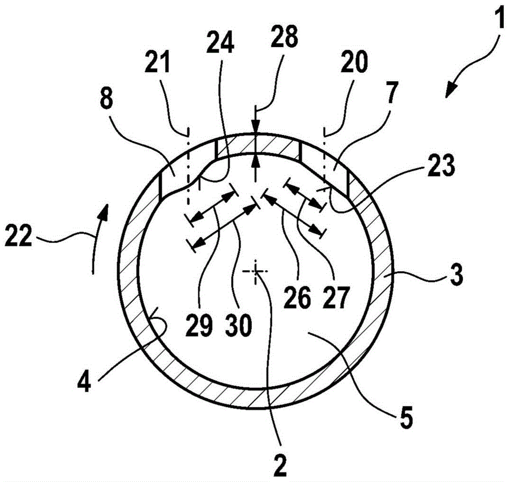
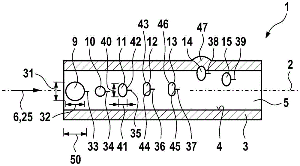
[0016] figure 1 The fuel distributor 1 is shown schematically in a cross-sectional view to illustrate possible configurations of the invention, wherein the cut plane is perpendicular to the longitudinal axis 2 ( figure 2 )orientation. The fuel distributor 1 has a tubular base body 3 . In particular, the tubular base body 3 is substantially hollow-cylindrical. Of course, it can also be in other configurations. For example, the tubular base body 3 has a decircular cross section. In order to simplify the illustration, other elements of the fuel distributor 1 are not shown. Such an element can in particular be a cup-shaped structure for connecting the fuel distributor 1 to the fuel injection valve.

[0017] The fuel distributor 1 can in particular be designed in the form of a fuel distributor pressure plate 1 . The fuel distributor 1 is especially suitable for hybrid compression externally ignited internal combustion engines. In particular, the fuel distributor 1 is here a...


PUM


Abstract

A fuel distributor (1), in particular for a fuel injection system of a hybrid compression external ignition internal combustion engine, the distributor comprises a tubular base body (3). Here, the inner wall ( 4 ) of the tubular base body ( 3 ) delimits an elongated fuel chamber ( 5 ). The tubular base body (3) is made of plastic. At least one through hole (7 to 15) is provided on the tubular base body (3), and the at least one through hole is centered at the inner wall (4) of the tubular base body (3) through the elongated The longitudinal axis ( 2 ) of the fuel chamber ( 5 ) opens into the fuel chamber ( 5 ) eccentrically. This improves the strength of the fuel distributor (1).

Description

technical field [0001] The invention relates to a fuel distributor, in particular for a fuel injection system of a hybrid compression external ignition internal combustion engine. In particular, the invention relates to the field of fuel injection systems designed as medium-pressure systems. Background technique [0002] In the case of fuel injection systems for motor vehicles, it is conceivable to use a fuel distributor plate made of steel or aluminium, suitable for high pressure applications. Thereby, a compressive strength of, for example, a pressure of 20 MPa (200 bar) is achieved. However, such a large and heavy configuration of rails suitable for high-voltage applications is associated with high manufacturing costs. [0003] Furthermore, fuel distributor platens suitable for low pressure applications from 0.3 MPa (3 bar) to 0.5 MPa (5 bar) are also available for the mentioned applications. Here, for example, thin-walled steel pipes can be used for the production of ...

Claims


Application Information

Patent Timeline
IPC IPC(8): F02M55/02F02M69/46B29C45/00
CPCF02M55/025F02M69/465F02M2200/03F02M2200/8046F02M2200/9015
Inventor H·克雷舍尔E·施特拉特曼M·法伊格尔H·乌里希N·豪特曼D·乌伦布洛克M·格纳
Owner ROBERT BOSCH GMBH
Why Eureka
Try Eureka