Eureka AIR delivers breakthrough ideas for toughest innovation challenges, trusted by R&D personnel around the world.

Shaft bottom leakage-proof plugging device for well cementation

A plugging device and anti-leakage technology, applied in wellbore/well components, sealing/isolation, earthwork drilling and production, etc., can solve problems such as improper operation, bottom hole leakage, and affecting cementing quality

Active Publication Date: 2014-01-15
XINJIANG GRAND OILFIELD TECH
View PDF11 Cites 2 Cited by
  • Summary
  • Abstract
  • Description
  • Claims
  • Application Information

AI Technical Summary

Problems solved by technology

However, due to the presence of leaking layers in the bottom hole formation or improper operation when running the casing into the well, the pressure is excited and the bottom hole leakage occurs.
Cause cement to flow out from the leakage layer after entering the bottom of the well, resulting in cement not being able to fully flow between the casing and the well wall, affecting the quality of cementing or causing cementing failure

Method used


Image

  • Shaft bottom leakage-proof plugging device for well cementation

Examples


Embodiment Construction

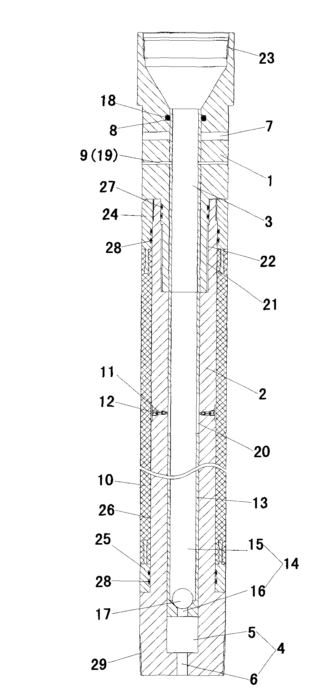
[0012] Such as figure 1 As shown, the bottom hole leakage prevention plugging device for well cementing of the present invention includes an upper joint 1 and a lower joint 2 made of copper material. The center of the upper joint 1 has a first through hole 3 . The upper end of the inner cavity wall of the first through hole 3 is processed with a sleeve special buckle 23 connected with the sleeve. The center of the lower joint 2 has a second through hole 4 . The second through hole 4 is a stepped hole formed by the first cylindrical hole 5 and the second cylindrical hole 6 . The diameter of the first cylindrical hole 5 is equal to the diameter of the first through hole 3 . The diameter of the first cylindrical hole 5 is larger than the diameter of the second cylindrical hole 6 , and the length of the first cylindrical hole 5 is much larger than the length of the second cylindrical hole 6 . The lower part of the outer surface of the upper joint 1 is processed with an externa...


PUM


Abstract

The invention discloses a shaft bottom leakage-proof plugging device for well cementation, and belongs to petroleum drilling well cementation construction operation. The shaft bottom leakage-proof plugging device comprises an upper connector and a lower connector which are connected with each other. The center of the upper connector is provided with a first through hole, and the center of the lower connector is provided with a second through hole. The second through hole is a big-end-up stepped hole which is composed of a first cylindrical hole and a second cylindrical hole. The outer surface of the upper connector is provided with a plurality of by-pass holes and shear pin holes in the circumferential direction, wherein the shear pin holes are located below the by-pass holes. An inner cavity of the upper connector is provided with an annular packing groove which is located above the by-pass holes. The outer surface of the lower connector is connected with a rubber sleeve in a sleeved mode. The middle portion of the lower connector is provided with a plurality of check valves in the circumferential direction. A valve seat barrel is mounted in the first through hole and the second through hole. A third through hole in the center of the valve seat barrel is a big-end-up stepped hole which is composed of a third cylindrical hole and a fourth cylindrical hole. Balls are placed on step surfaces. Packing is mounted between the upper portion of the valve seat barrel and the packing groove. The valve seat barrel is connected with the upper connector through a plurality of shear pins. The valve seat barrel is provided with a plurality of fourth through holes communicated with the check valves. The shaft bottom leakage-proof plugging device can guarantee smooth proceeding of a cement job and cementing quality, and is simple in structure and convenient to install.

Description

technical field [0001] The invention relates to an oil well cementing construction operation, in particular to a well bottom leak-proof plugging device for well cementing. Background technique [0002] In cementing operations in petroleum, geological drilling and other fields, after drilling to the designed well depth, it is necessary to run the casing into the well, and inject cement from the inner cavity of the casing, so that the cement flows into the bottom of the well, and then flows out of the casing into the casing and Between the well walls, the continuously entering cement gradually rises until the entire space between the casing and the well wall is filled from bottom to top, so that the casing and the well wall are fixed together to strengthen the well wall. However, due to the presence of leaking layers in the bottom hole formation or improper operation when running the casing into the well, pressure surges are formed, resulting in bottom hole leakage. After the...

Claims


Application Information

Patent Timeline
IPC IPC(8): E21B33/12
Inventor 贺志刚李怀仲贾应林陈力力劳纯宇
Owner XINJIANG GRAND OILFIELD TECH
Why Eureka
Eureka Blog
Learn More