Centripetal joint bearing with spiral groove on internal diameter

A technology of joint bearings and spiral grooves, which is applied to bearing components, shafts and bearings, sliding contact bearings, etc., can solve the problems of low processing efficiency, easy wear and sticking of inner diameter and shaft, and less oil storage in lubricating grooves. Product quality and process efficiency, improved process operability, reduced wear and seizing effects

Inactive Publication Date:
View PDF6 Cites 6 Cited by
  • Summary
  • Abstract
  • Description
  • Claims
  • Application Information

AI Technical Summary

Problems solved by technology

[0002] In the existing radial spherical plain bearings, in order to fully lubricate, several lubricating circular arc grooves perpendicular to the end surface are provided on the surface of the inner diameter, so that the lubricating groove stores less oil, and the oil supply to the inner diameter and the sliding contact surface of the shaft is not sufficient and uniform , the inner diameter and shaft are easy to wear and stick, which cannot meet the needs of automobile brake drums. This kind of lubricating circular arc groove perpendicular to the end surface will cause the grinding wheel and the workpiece groove to engage the knife intermittently during grinding, and the grinding wheel shaft will produce elastic deformation. The size of the edge of the groove is large, the rejection rate is high, and the workmanship is poor
In addition, processing requires special equipment, and the processing efficiency is low

Method used


Image

  • Centripetal joint bearing with spiral groove on internal diameter

Examples


Embodiment Construction

[0012] Below in conjunction with accompanying drawing and embodiment, the present invention is described in further detail:

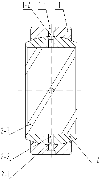
[0013] like figure 1 As shown, the present invention is composed of an outer ring 1 and an inner ring 2, the inner surface of the outer ring 1 and the outer surface of the inner ring 2 are sliding contact surfaces, the inner surface of the outer ring 1 is an inner spherical surface, the outer surface of the inner ring 2 is an outer spherical surface, and the outer surface of the outer ring 2 is an outer spherical surface. There is an annular outer ring outer diameter lubricating groove 1-1 and an outer ring lubricating oil hole 1-2 at the center of the outer diameter width of ring 1; there is an annular outer ring outside the inner ring at the center of the outer spherical surface width of inner ring 2 that is perpendicular to the center line of the inner hole. Spherical lubricating groove 2-1 and inner ring lubricating oil hole 2-2, inner ring inner di...


PUM


Abstract

The invention discloses a centripetal joint bearing with a spiral groove on its internal diameter, which belongs to the technical field of centripetal joint bearings. The invention mainly aims to overcome the problems of small oil storage at inner diameters and insufficient and nonuniform oil supply of conventional centripetal joint bearings in the prior art. The centripetal joint bearing provided by the invention is mainly characterized by comprising an outer ring and an inner ring, wherein the external surface of the outer ring is provided with an outer ring outer diameter lubrication groove and two symmetrical outer ring lubricating oil holes, the outer spherical surface of the inner ring is provided with an inner ring outer spherical surface lubrication groove, which is perpendicular to the center line of an inner hole, and four uniformly distributed inner ring lubricating oil holes, the inner diameter surface of the inner ring is provided with two inner ring inner diameter spiral lubrication grooves, and the two inner ring inner diameter spiral lubrication grooves are intersected with the inner ring lubricating oil holes. The centripetal joint bearing provided by the invention has the characteristics of increase of oil storage in an inner diameter surface groove, reduction of abrasion and clamping stagnation between the inner diameter and a shaft, prolongation of the service life of the bearing, improvement of process operability, enhancement of product quality and working efficiency, etc. and is mainly applicable to centripetal joint bearings which are in need of good lubrication conditions, an automobile brake drum, a low speed and heavy load.

Description

technical field [0001] The invention belongs to the technical field of radial joint bearings, in particular to a radial joint bearing with two spiral grooves on the inner diameter of the bearing. Background technique [0002] In the existing radial spherical plain bearing, in order to fully lubricate, several lubricating arc grooves perpendicular to the end face are arranged on the inner diameter surface, so that the oil storage in the lubricating groove is small, and the oil supply to the inner diameter and the sliding contact surface of the shaft is not sufficient and uniform. , The inner diameter and shaft are easy to wear and stick, which cannot meet the needs of automobile brake drums. This type of lubricated arc grooves perpendicular to the end face, the grinding wheel and the workpiece groove intermittently engage the knife during grinding, and the grinding wheel shaft produces elastic deformation and concave grooves. The size of the slot edge is large, the scrap rate...

Claims


Application Information

Patent Timeline
Patent Type & Authority Applications(China)
IPC IPC(8): F16C23/04F16C33/04F16N1/00
Inventor 杨中良赵志强肖壮勇李春晖王恩来安艳芹
Why Eureka
Try Eureka