
Electronic anticorrosion system of electric water heater

An electronic anti-corrosion, electric water heater technology, applied in water heaters, fluid heaters, lighting and heating equipment, etc., can solve the problems of decreased heating efficiency, shortened life, and no continuous power supply, achieving good anti-corrosion effect and slowing down Effect of fouling speed

Active Publication Date: 2014-01-15
何刚
View PDF6 Cites 4 Cited by
  • Summary
  • Abstract
  • Description
  • Claims
  • Application Information

AI Technical Summary

Problems solved by technology

[0006] 2. Metal magnesium turns into magnesium ions in the process of consumption. In the oxidation-reduction reaction in the water heater system (also known as the primary battery reaction), magnesium is used as the anode, and the exposed liner and the joining tube are used as the cathode, and the magnesium ions will Approaching the heating tube, forming magnesium carbonate and scaling on the heating tube, causing the heating tube to not release heat smoothly, the heating efficiency decreases, the temperature of the heating tube rises, and the service life is shortened
However, this method still has certain limitations:
[0010] 2. There is still the problem of fouling of the heating tube. Although there is no magnesium ion, because the effect of the applied electric field is stronger than the original battery reaction between the original magnesium and the two poles of the heating tube, the original cations in the water (mainly metal cations) Closer to the heating pipe, thus fouling
[0011] 3. This method does not provide continuous power supply
For the consideration of energy saving and safety, many users will turn off the power during or after using the electric water heater. Once the power is turned off, the device will lose its function

Method used


Image

  • Electronic anticorrosion system of electric water heater
  • Electronic anticorrosion system of electric water heater
  • Electronic anticorrosion system of electric water heater

Examples


Embodiment Construction

[0042] The preferred embodiments of the present invention will be described below in conjunction with the accompanying drawings. It should be understood that the preferred embodiments described here are only used to illustrate and explain the present invention, and are not intended to limit the present invention.

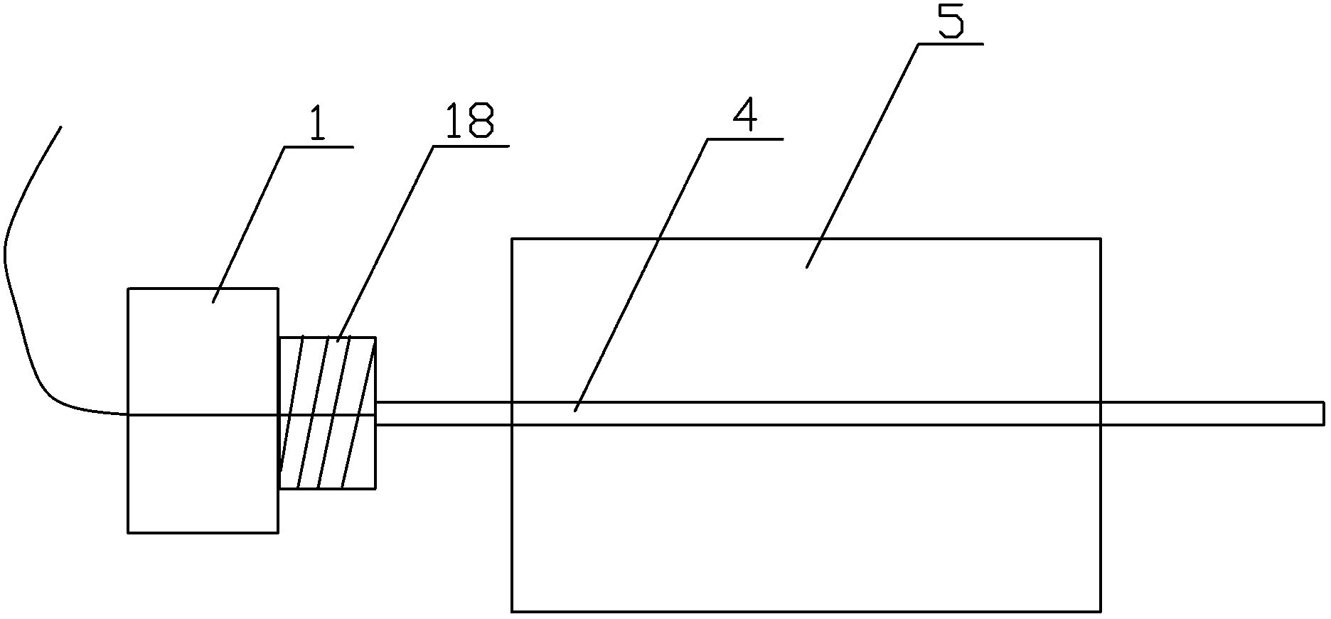
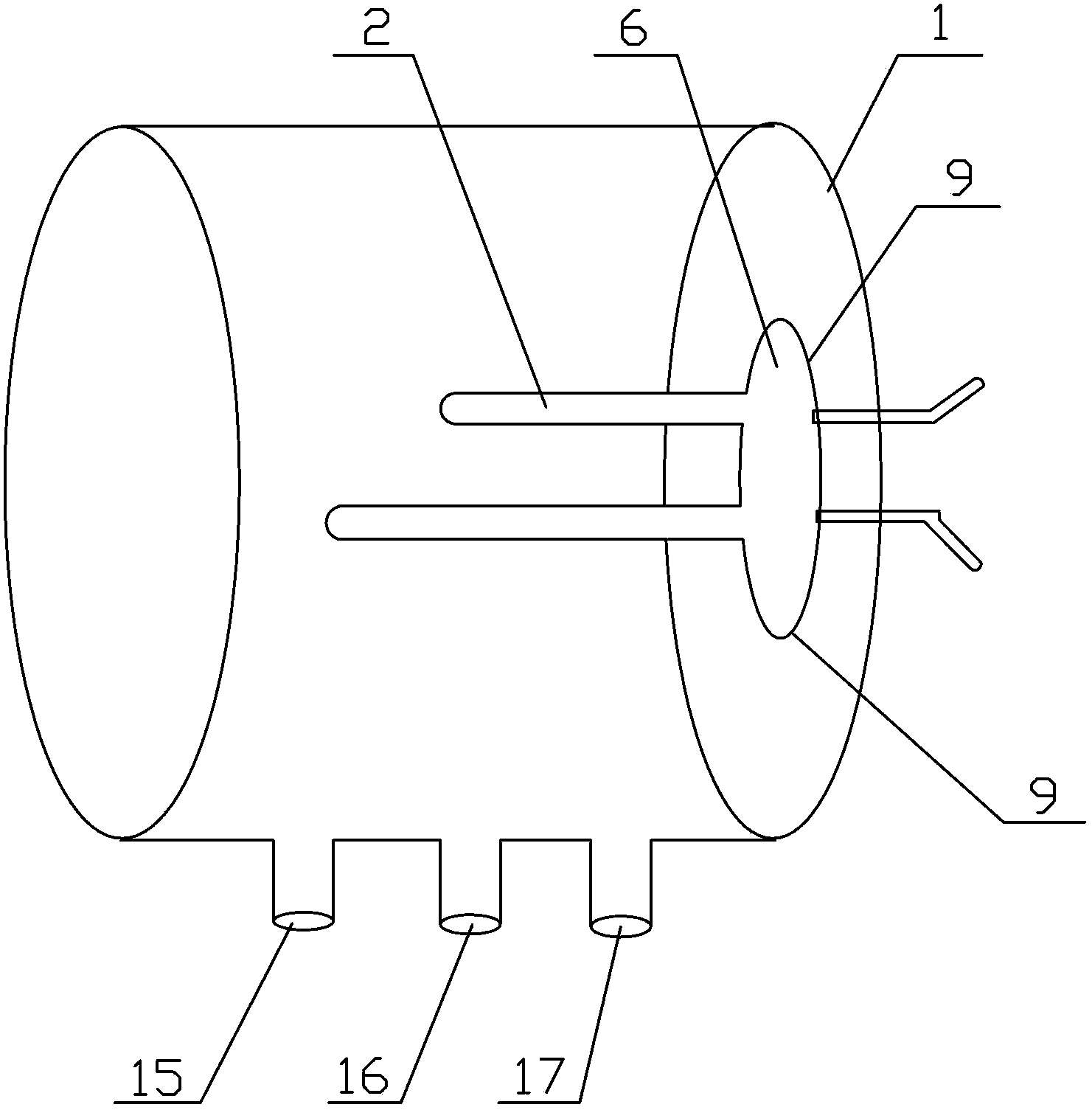
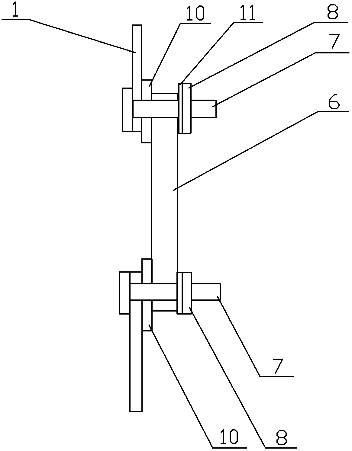
[0043] Such as Figure 1 to Figure 4 As shown, the electric water heater electronic anticorrosion system of the present invention includes a power supply, an inner tank 1, a heating rod 2, an anode 3 and a titanium rod 4, the anode 3 and the heating rod 2 are respectively fixed on the inner tank 1, and the lower end of the anode 3 and the The titanium rod 4 is connected, and the titanium rod 4 is fixed with a titanium sheet 5. Adding a titanium sheet 5 or other inert conductors on the anode 3 increases the surface area of ​​the anode 3. The ratio of the area of ​​the titanium sheet 5 to the inner area of ​​the liner 1 is about 100-200CM 2 / 1M 2 The titanium sheet 5...


PUM


Abstract

The invention discloses an electronic anticorrosion system of an electric water heater. The electronic anticorrosion system comprises a power source, an inner container, a heating bar, an anode and a titanium bar. The anode and the heating bar are fixed on the inner container, the lower end of the anode is connected with the titanium bar, the anode is connected with the positive electrode of the power source, the inner container is connected with the negative electrode of the power source, and the heating bar, the anode and the inner container are fixedly connected in an insulation mode. Compared with traditional magnesium bar anticorrosion, the electronic anticorrosion system is good in anticorrosion effect, no more dirty can be generated on the heating bar due to corrosion of magnesium, although the electronic anticorrosion system creates an electrode environment for the water environment in the inner container, the cathode and the anode of the heating bar are separated in an insulating mode, and therefore the heating bar can not be corroded, and the scaling speed of the heating bar is greatly relieved.

Description

technical field [0001] The invention relates to an anticorrosion system, in particular to an electronic anticorrosion system for an electric water heater. Background technique [0002] In order to prevent the inner tank of the water heater from being corroded, the current industry mainly adopts the method of installing metal magnesium rods at the sewage outlet of the inner tank of the water heater. Due to the high activity of magnesium metal, corrosive ions (headed by chloride ions) in the water will be destroyed. Attraction, the magnesium metal is first corroded, thus protecting the metal liner. [0003] Most of the current electric water heaters are still using this traditional method. [0004] The current metal magnesium anticorrosion method adopted by water heaters has the following defects: [0005] 1. Metal magnesium is a consumable material during use. The water in the water heater is constantly replaced, and the metal magnesium is also constantly corroded. Especial...

Claims


Application Information

Patent Timeline
Patent Type & Authority Applications(China)
IPC IPC(8): F24H1/20C23F14/00
Inventor 何刚
Owner 何刚
Learn More