Nested-type energy-saving nozzle and nozzle system with same

A nested, nozzle technology, applied in the direction of spraying devices, spraying devices, liquid spraying devices, etc., can solve the problems of increasing gas source, equipment and electricity costs, waste, etc., to avoid safety hazards and improve surface finish.

Active Publication Date: 2014-01-22
启东通润润滑液压设备有限公司
View PDF5 Cites 12 Cited by
  • Summary
  • Abstract
  • Description
  • Claims
  • Application Information

AI Technical Summary

Problems solved by technology

[0003] At present, lubricants such as coolants, emulsions or cutting oils are mostly used in the existing metal processing lubrication and cooling, and these types of lubricants are used in large quantities during metal processing Spraying on the processing part is usually carried out by uninterrupted showering, so that the same cooling and lubrication is carried out on other parts that do not need cooling and lubrication, resulting in a large amount of cooling medium, causing waste and polluting the environment
In recent years, the research on minimal quantity lubrication technology has made great progress, which has reduced the harm caused by the discharge of a large amount of cutting oil to the environment. However, in many processing processes, it is often difficult to effectively solve the cooling problem, and the minimum quantity lubrication device mainly uses compressed air. Take away the heat generated by friction and the debris generated by processing, and the air consumption is large. If a processing workshop uses multiple sets of micro-lubrication devices, it is often necessary to increase the air source, thus increasing the cost of equipment and electricity
At the same time, because the micro-lubrication device uses compressed air as power, it often makes the sprayed lubricant atomized seriously, which affects the health of workers and the environment.

Method used


Image

  • Nested-type energy-saving nozzle and nozzle system with same
  • Nested-type energy-saving nozzle and nozzle system with same
  • Nested-type energy-saving nozzle and nozzle system with same

Examples


Embodiment Construction

[0062] Now, the present invention will be described in further detail in conjunction with the accompanying drawings and specific embodiments. These drawings are all simplified schematic diagrams, which only illustrate the basic structure of the present invention in a schematic manner, so they only show the configurations related to the present invention.

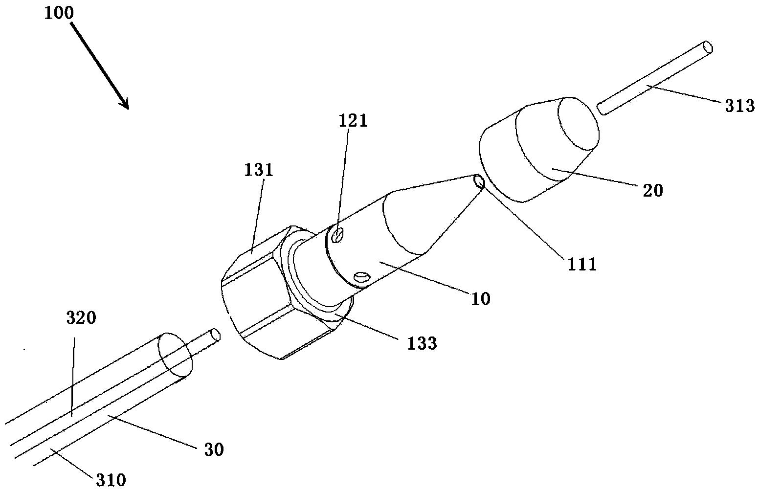
[0063] Such as figure 1 The nozzle system 100 provided in this embodiment including nested energy-saving nozzles includes a nozzle body 10 , a nesting ring 20 and a gas-liquid input mechanism 30 .

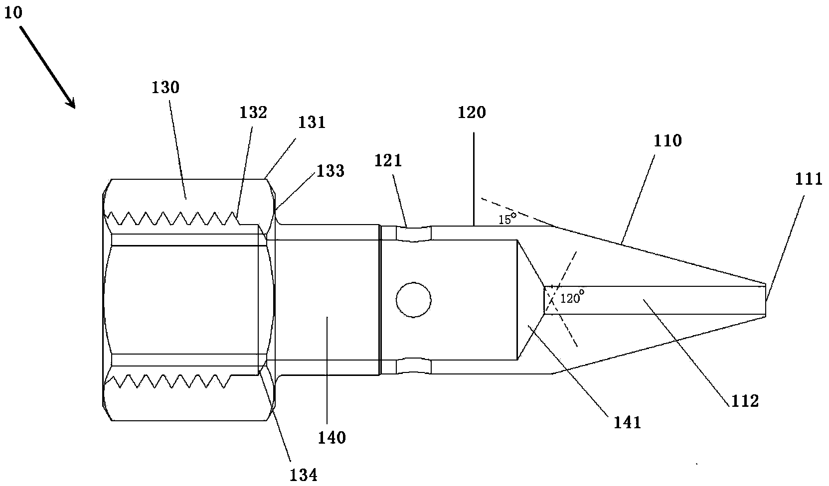
[0064] Such as figure 2 The illustrated nozzle body 10 includes a head 110 , a middle 120 and a bottom 130 .

[0065] The head 110 of the nozzle body 10 is a cone, and the top is provided with an injection hole 111; the middle part 120 of the nozzle body 10 is a cylinder, and four air holes 121 are evenly arranged on the cylinder; the bottom 130 of the nozzle body 10 is a thread structure .

[0066] Wherein, the cylinder an...


PUM


Abstract

The invention provides a nested-type energy-saving nozzle which comprises a nozzle body and a nesting ring. The nested-type energy-saving nozzle is characterized in that the nozzle body comprises a head portion, a middle portion and a bottom portion; the head portion of the nozzle body is a conic body and a jet hole is formed in the top end of the head of the nozzle body; the middle of the nozzle body is a cylindrical body and at least two air holes are evenly formed in the cylindrical body; the bottom portion of the nozzle body is of a threaded structure; the nesting ring is matched with the middle portion of the nozzle body so that a gap structure can be formed, wherein an inner cavity with a conic top is formed in the nozzle body and a fluid channel communicated with the jet hole is further formed in the top of the inner cavity. After the nested-type energy-saving nozzle is installed in a metal machining lubricating device, point lubrication is achieved, the problem that gas consumption for metal near-dry machining lubrication is large in the prior art is solved, power sources are saved, and the nested-type energy-saving nozzle has the advantages of saving lubricating oil and being more environmentally friendly.

Description

technical field [0001] The invention relates to a nozzle device, in particular to a nested energy-saving nozzle and a nozzle system comprising the nozzle. Background technique [0002] In the field of traditional machining, metal processing usually involves cutting, grinding, drilling, tapping, bending and other processing processes that easily cause the workpiece to heat up sharply. This type of processing requires frictional contact between workpieces, and timely lubrication should usually be carried out . [0003] At present, the existing metal processing lubrication and cooling mostly use lubricants such as coolants, emulsions or cutting oils. These types of lubricants are sprayed on the processing parts in large quantities during metal processing, usually in the form of uninterrupted showering. , In this way, the same cooling and lubrication are carried out in other parts that do not need cooling and lubrication, resulting in a large amount of cooling medium, causing w...

Claims


Application Information

Patent Timeline
Patent Type & Authority Applications(China)
IPC IPC(8): B05B1/06B05B1/34B05B7/06
CPCB05B1/06B05B1/34B05B7/067
Inventor 李刚张乃庆吴启东
Owner 启东通润润滑液压设备有限公司
Why Eureka
Try Eureka