Lifting type sheet metal part punching device

A sheet metal parts, lift-type technology, applied in the field of lift-type sheet metal punching devices, can solve the problem of inability to achieve high-quality, high-efficiency punching, uneven force on the punched parts, easy damage to the cut edge, etc. problems, to avoid uneven stress, solve the limited expansion length, and ensure product quality

Inactive Publication Date: 2014-01-22
HOTOLI GUANGDONG ELECTRIC CO LTD
View PDF8 Cites 4 Cited by
  • Summary
  • Abstract
  • Description
  • Claims
  • Application Information

AI Technical Summary

Problems solved by technology

[0006] Aiming at the problems that the existing punching device for sheet metal parts does not have a wide application range, the force of the punched parts is uneven, the edge to be cut is easily damaged, and high-quality and high-efficiency punching cannot be realized, the present invention provides a lifting type sheet metal punching device. Piece punching device, which adds a telescopic piston to realize the lifting of the whole punching tool, adopts the guide sleeve with balls to cooperate with the guide column, so that the sliding of the guide sleeve is more continuous, smooth and stable, and the tapered cutout can be used. achieve high quality

Method used


Image

  • Lifting type sheet metal part punching device
  • Lifting type sheet metal part punching device
  • Lifting type sheet metal part punching device

Examples


Embodiment 1

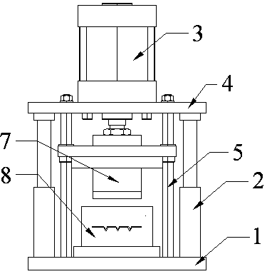
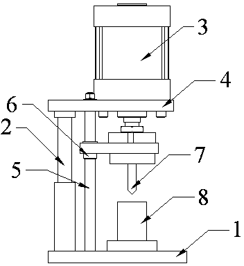
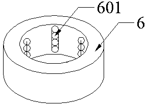
[0027] Such as figure 1 , figure 2 as well as image 3 As shown, a lift-type sheet metal punching device includes a base plate 1, a punch 8 and a die 9, and also includes a telescopic looper 2, a cylinder 3, a guide rod 5, a guide sleeve 6, and a punch seat 7, and the cylinder 3 is located on the top plate 4, the piston of the cylinder 3 is connected to the middle part of the punch seat 7; the telescopic looper 2 and the guide rod 5 are fixed on the side of the bottom plate 1 away from the feed port; the top of the telescopic looper 2 is fixed on the top plate 4 the lower surface; the guide rod 5 passes through the top plate 4 and is fixed with a nut; the guide sleeve 6 is set on the guide rod 5 and is connected with the two ends of the punch seat 7; the guide sleeve 6 is also provided with a ball 601; the punch 8 is fixed on Below the punch seat 7, and the shape of the lower end surface is conical.

[0028] In addition, there are two telescopic loopers 2, which are distr...

Embodiment 2

[0031] Same as embodiment 1, the difference is that the taper angle of the tapered portion of the lower end surface of the punch 8 is 40°, which reduces the contact area and better realizes punching under the premise of ensuring that the die is not damaged.

Embodiment 3

[0033] Same as embodiment 1, the difference is that there are 4 guide rods to ensure more stable and reliable work of the punching tool and to obtain better quality sheet metal parts.


PUM

PropertyMeasurementUnit
angleaaaaaaaaaa

Abstract

The invention belongs to the technical field of sheet metal part machining equipment, and particularly relates to a lifting type sheet metal part punching device. The lifting type sheet metal part punching device comprises a retractable movable sleeve, an air cylinder, a guide rod, a guide sleeve and a male die base. The air cylinder is located on a top plate, and a piston of the air cylinder is connected with the middle of the male die base. The retractable movable sleeve and the guide rod are fixed on one side, far away from a feed port, of a bottom plate. The top end of the retractable movable sleeve is fixed to the lower surface of the top plate. The guide rod penetrates through the top plate and is fixed through a nut. The guide rod is sleeved with the guide sleeve, and the guide sleeve is connected with the two ends of the male die base. A roll ball is arranged inside the guide sleeve, a male die is fixed below the male die base, and the lower end face of the male die is in a conical shape. According to the lifting type sheet metal part punching device, a whole punching tool can ascend and descend through the additionally arranged retractable piston. The guide sleeve with the roll ball is matched with a guide column, so that the guide sleeve slides more continuously, smoothly and stably. A conical notch is adopted so that high quality can be achieved. The cutting can be carried out efficiently.

Description

technical field [0001] The invention belongs to the technical field of sheet metal parts processing equipment, and in particular relates to a lifting type sheet metal part punching device. Background technique [0002] Sheet metal parts are products processed by sheet metal technology. They have the characteristics of light weight, high strength, electrical conductivity (can be used for electromagnetic shielding), low cost, and good mass production performance. Instruments and other fields have been widely used. For example, in computer cases, mobile phones, and MP3 players, sheet metal parts are an indispensable part. Sheet metal parts are fabricated by filament power winding, laser cutting, heavy machining, metal bonding, metal drawing, plasma cutting, precision welding, roll forming, sheet metal bending, die forging, water jet cutting, precision welding . Among them, the cutting of sheet metal parts is especially common. [0003] In the prior art, a cylinder is often u...

Claims


Application Information

Patent Timeline
Patent Type & Authority Applications(China)
IPC IPC(8): B21D28/02B21D28/14
Inventor 张天松胡仁农
Owner HOTOLI GUANGDONG ELECTRIC CO LTD
Why Eureka
Try Eureka