Method for target material component welding

A welding method and component technology, applied in welding equipment, non-electric welding equipment, metal processing equipment, etc., can solve the problems of poor welding bonding rate of target components, inability to meet long-term stable production and use of target components, low welding efficiency, etc. , to achieve a good sputtering effect, to meet the long-term stable production and use of the target effect

Inactive Publication Date: 2014-01-22
KONFOONG MATERIALS INTERNATIONAL CO LTD
View PDF1 Cites 13 Cited by
  • Summary
  • Abstract
  • Description
  • Claims
  • Application Information

AI Technical Summary

Problems solved by technology

[0006] The technical problem to be solved by the present invention is that the welding efficiency is low when the aluminum target and the copper back plate are welded together by the existing welding method, and the formed target assembly has poor welding bonding rate, low welding strength, large deformation, and The internal structure of the aluminum target in the target assembly does not meet the sputtering requirements, so it cannot meet the needs of long-term stable production and use of the target assembly

Method used


Image

  • Method for target material component welding
  • Method for target material component welding
  • Method for target material component welding

Examples


Embodiment 1

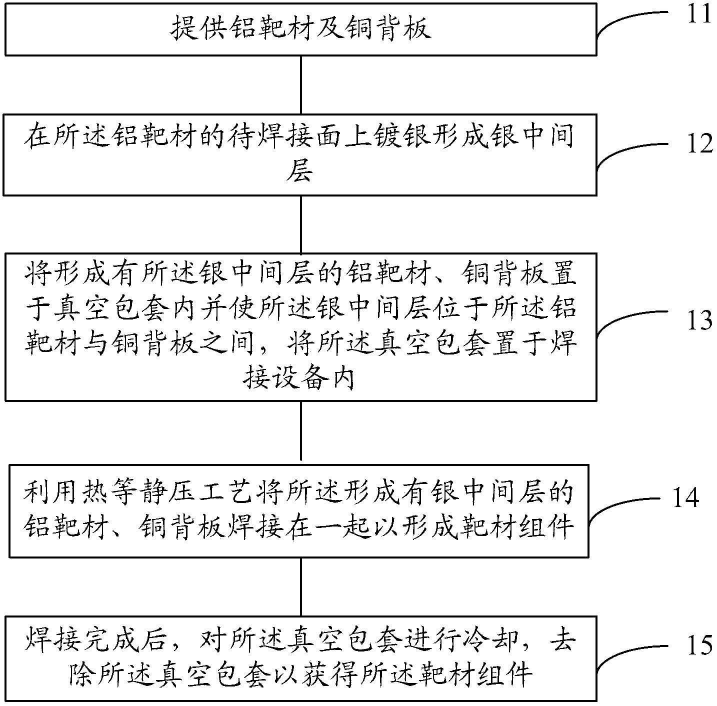
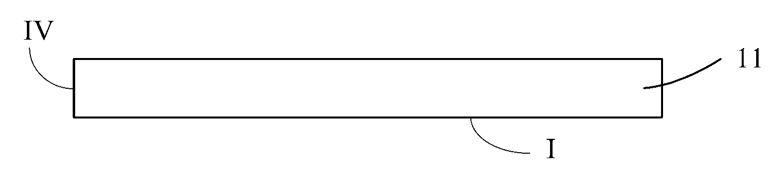
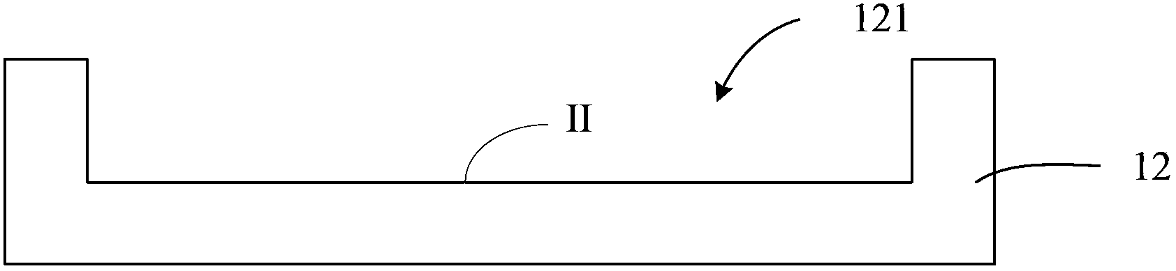
[0051] first reference figure 2 and image 3 ,implement figure 1 In step S11, an aluminum target 11 and a copper back plate 12 are provided.

[0052] Please continue to refer figure 2 , the purity of the aluminum target material 11 in this embodiment is at least 99.9995%. According to the actual requirements of the application environment and sputtering equipment, the shape of the aluminum target 11 can be a cylinder, a cuboid, a cube, or a cone, and the cross-section can be any of circular, triangular, or other similar shapes (including regular shapes and irregular shapes). A kind of cylinder, preferably a cylinder. The diameter of the aluminum target 11 is a machining allowance of 2 mm to 5 mm added to the design size, and the thickness dimension is a machining allowance of 1 mm to 3 mm added to the design size. The purpose of setting the processing allowance is to provide a relatively large processing space for the aluminum target 11 in the subsequent mechanical proc...

Embodiment 2

[0121] The difference between the second embodiment and the first embodiment is that the method of plating silver on the surface I to be welded of the aluminum target 11 to form the silver intermediate layer 13 is electroplating.

[0122] Electroplating is the process of using the principle of electrolysis to plate silver on the surface of the aluminum target to be welded to form a silver intermediate layer. During electroplating, the silver metal is used as the anode, which is oxidized into cations and enters the electroplating solution; the surface of the aluminum target to be welded is used as the cathode, and the cations of the silver coating are reduced on the surface of the aluminum target to be welded to form a silver coating. In order to eliminate the interference of other cations and make the silver coating uniform and firm, it is necessary to use a solution containing silver ions as the electroplating solution to keep the concentration of silver ions in the silver coa...


PUM

PropertyMeasurementUnit
thicknessaaaaaaaaaa
thicknessaaaaaaaaaa
current densityaaaaaaaaaa

Abstract

The invention provides a method for target material component welding. The method comprises the following steps that an aluminum target material and a copper back board are provided; silver is plated on a face to be welded of the aluminum target material to form a silver middle layer; the aluminum target material with the silver middle layer and the copper back board are placed in a vacuum bag, the silver middle layer is located between the aluminum target material and the copper back board, and the vacuum bag is arranged in a welding device; the hot isostatic pressure technology is used for welding the aluminum target material with the silver middle layer and the copper back board together to form a target material component; after welding is completed, the vacuum bag is cooled and removed, so that the target material component is obtained. The method is high in welding efficiency, the formed target material component is good in welding binding rate, high in welding strength and small in deformation, the internal organization structure of the aluminum target material in the target material component meets the sputtering requirement, and therefore requirements for long-time stable production and using of target materials can be met.

Description

technical field [0001] The invention relates to the field of manufacturing semiconductor sputtering targets, in particular to a welding method for target components. Background technique [0002] In the semiconductor industry, the target assembly is composed of a target that meets the sputtering performance and a back plate that can be combined with the target and has a certain strength. The back plate can play a supporting role when the target assembly is assembled to the sputtering base, and has the effect of conducting heat. [0003] During the sputtering process, the working environment of the target assembly is relatively harsh. The ambient temperature of the target assembly is relatively high, such as 300°C to 600°C; in addition, one side of the target assembly is cooled by cooling water, while the other side is at 10 -9 In the high vacuum environment of Pa, a huge pressure difference is formed on the opposite sides of the target assembly; moreover, the target assemb...

Claims


Application Information

Patent Timeline
Patent Type & Authority Applications(China)
IPC IPC(8): B23K20/02B23K20/14B23K20/24
CPCB23K20/021B23K20/023B23K20/14B23K20/24C23C14/3414
Inventor 姚力军相原俊夫大岩一彦潘杰王学泽李超
Owner KONFOONG MATERIALS INTERNATIONAL CO LTD
Why Eureka
Try Eureka