
Silicon block cutting method and cutting device thereof

A cutting method and a technology of a cutting device, which are applied to fine working devices, stone processing equipment, manufacturing tools, etc., can solve the problems of easy generation of chips, gaps, and surface loss of silicon wafers, so as to improve stability, reduce shaking, and reduce The effect of edge collapse

Inactive Publication Date: 2016-05-25
JIANGXI SAI WEI LDK SOLAR HI TECH CO LTD
View PDF7 Cites 0 Cited by
  • Summary
  • Abstract
  • Description
  • Claims
  • Application Information

AI Technical Summary

Problems solved by technology

During the cutting process, due to the shaking of the steel wire, it is easy to cause damage to the surface of the silicon wafer, resulting in edge chipping, gaps, hidden cracks, slivers, etc. prone to debris

Method used


Image

  • Silicon block cutting method and cutting device thereof
  • Silicon block cutting method and cutting device thereof
  • Silicon block cutting method and cutting device thereof

Examples


Embodiment Construction

[0026] The following will clearly and completely describe the technical solutions in the embodiments of the present invention with reference to the drawings in the embodiments of the present invention.

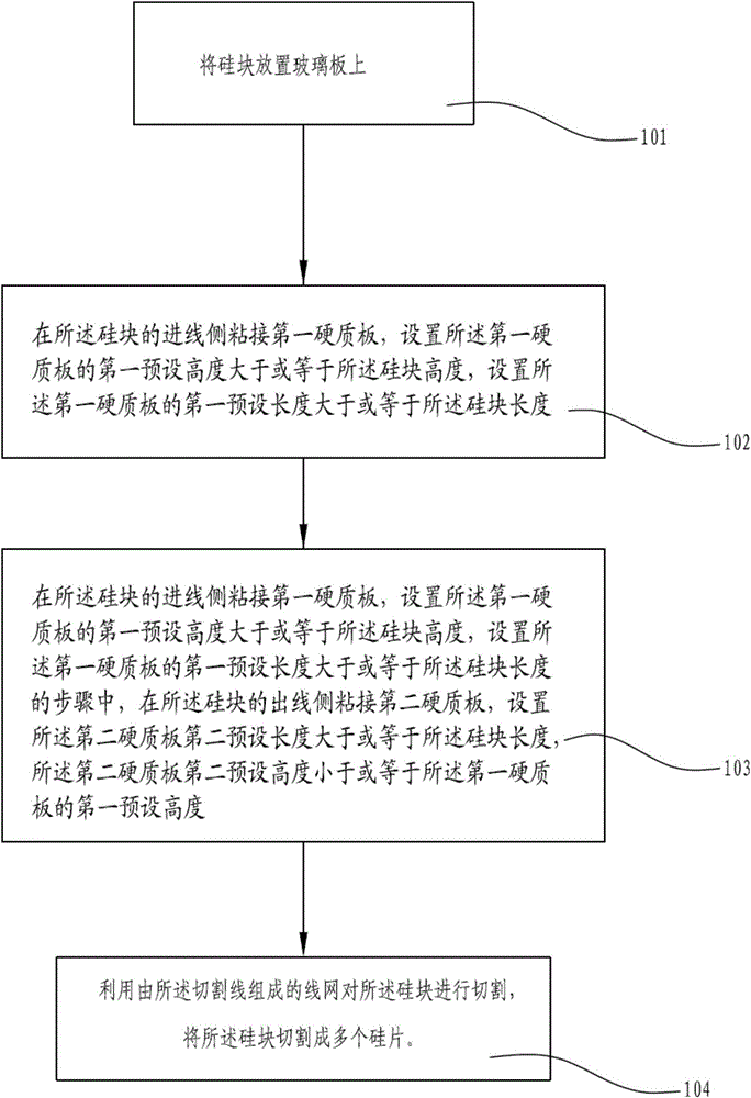
[0027] see figure 1 , a silicon block cutting method according to Example 1 provided in the implementation mode of the present invention. The method includes the following steps:

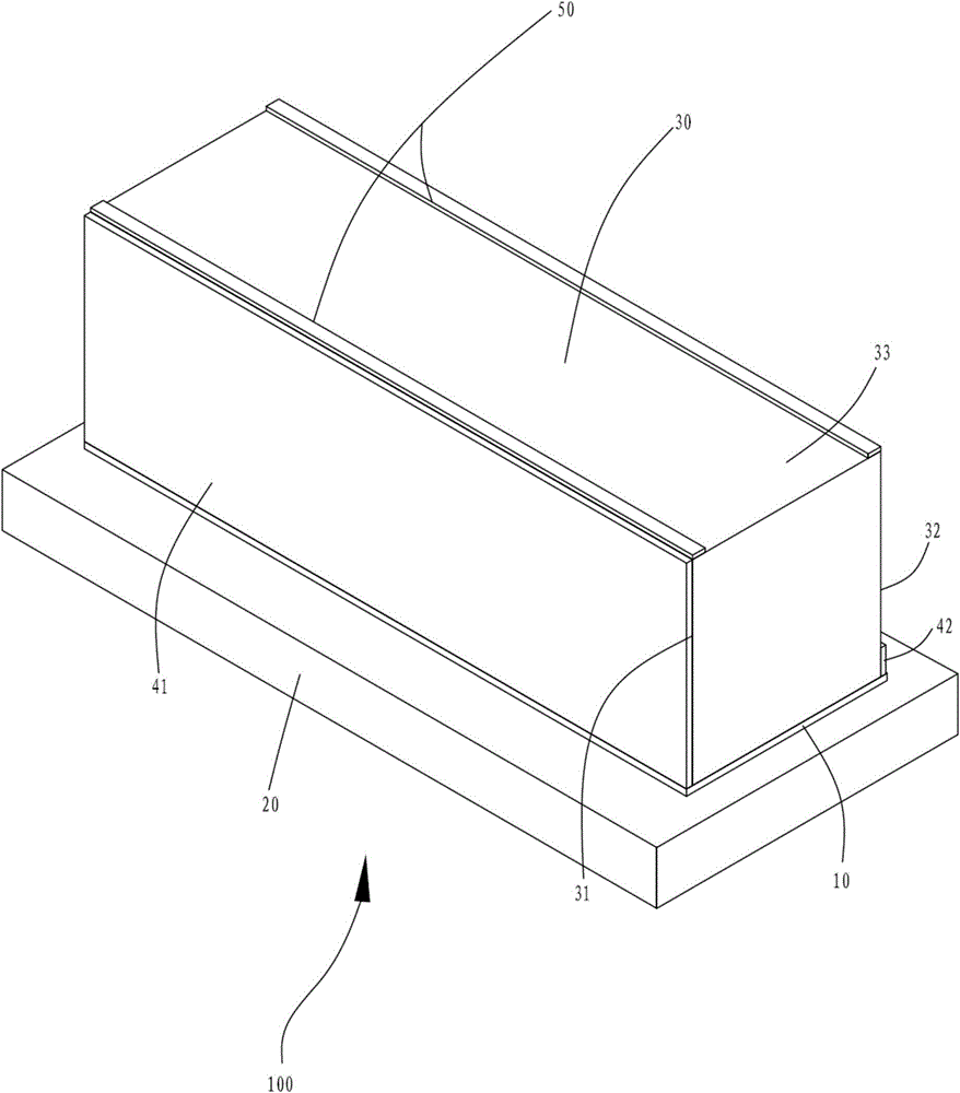
[0028] Step 101: Place the silicon block on the glass plate. In this embodiment, the silicon block has a length of 480 mm, a width of 150 mm, and a height of 156 mm, and the glass plate has a length of 480 mm, a width of 165 mm, and a thickness of 5 mm. Certainly, in other implementation manners, the silicon block and the glass plate may also have other dimensions. Specifically, the bottom surface of the silicon block is coated with glue. And place the bottom surface coated with glue on the glass plate in the center, and the length direction of the silicon block is consistent with the length dir...


PUM

PropertyMeasurementUnit
thicknessaaaaaaaaaa
thicknessaaaaaaaaaa
thicknessaaaaaaaaaa

Abstract

A silicon briquette cutting method includes: placing a silicon briquette on a glass plate; adhering a first hard board to the wire feed side of the silicon briquette, setting the first preset height of the first hard board to be not smaller than the height of the silicon briquette, and setting the first preset length of the first hard board to be not smaller than the length of the silicon briquette; using a wire net formed by cutting wires to cut the silicon briquette into multiple silicon wafers. The invention further provides a silicon briquette cutting device used by the cutting method. By the cutting method and device, silicon wafer cutting point hidden crack, crack and notch proportion during silicon briquette cutting is reduced, cutting yield is increased, TTV value of the silicon wafer is reduced, and silicon loss is reduced.

Description

technical field [0001] The invention relates to the field of silicon block processing technology, in particular to a silicon block cutting method and a cutting device thereof. Background technique [0002] The core of modern silicon block cutting is that the cutting wire mesh completes the cutting action with the cooperation of abrasive slurry. Up to 1000 cutting wires are wound parallel to each other on the guide wheel to form a horizontal cutting wire "net". Motor-driven guide wheels move the entire cutting wire web at a speed of 5 to 25 meters per second. The speed of the cutting line, linear or back and forth, is adjusted to the shape of the ingot throughout the cutting process. During the movement of the cutting wire, the nozzle continuously sprays an abrasive slurry containing suspended silicon carbide particles towards the cutting wire. Silicon blocks are fixed on the cutting table, usually 4 blocks at a time. The cutting table passes vertically through the moving...

Claims


Application Information

Patent Timeline
Patent Type & Authority Patents(China)
IPC IPC(8): B28D5/04
Inventor 李建彭也庆章金兵
Owner JIANGXI SAI WEI LDK SOLAR HI TECH CO LTD
Learn More